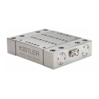
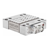
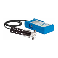
This document describes the Kistler Type 9139AA Multicomponent Dynamometer, designed for dynamic and quasistatic measurement of forces up to 30 000 N. It measures the three orthogonal components (Fx, Fy, and Fz) of any force acting on its cover plate. The dynamometer is extremely rigid, resulting in a high natural frequency, and offers high resolution, allowing the measurement of small dynamic changes even within large forces. It measures the active force irrespective of its application point, capturing both the average force value and the dynamic part of the force signal. The useful frequency range primarily depends on the natural frequency of the entire measurement setup.
Functional Principle:
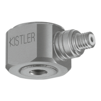
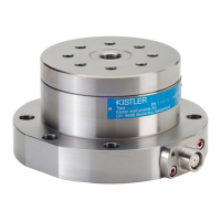
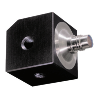
The force to be measured is applied via a cover plate and distributed to four 3-component force sensors, which are arranged between the cover plate and two base plates. Each force sensor contains three quartz crystal plate pairs: one sensitive to pressure in the z-direction and two sensitive to shear in the x and y-directions. This design ensures practically no deflection during measurement. The applied force is split into three components across these four sensors. For 3-component force measurement, the individual signals are combined in the connecting cable. Depending on the force direction, positive or negative charges are produced at the connections. Negative charges result in positive voltages at the charge amplifier output, and vice versa. The dynamometer is designed to ensure that acting forces do not exert any torque on individual force sensors, allowing them to be loaded up to their maximum measuring range (zero torque). However, a force with a line of action that does not pass through the dynamometer's zero point will generate torque, which can cause sensors to experience additional load. For 3-component force measurement, the output signals of the four sensors (Fx, Fy, and Fz) are added together, always yielding the correct total value regardless of the force application point. Depending on the force application point, the load can be distributed among all four sensors or predominantly taken by a single sensor. If the force acts far from the force platform, a single sensor might experience several times the measured force due to the lever principle.
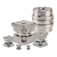
Construction:
The dynamometer consists of four 3-component force sensors mounted under high preload between two base plates and one cover plate. This preload is essential for friction force transmission. The four force sensors are ground-isolated, which largely eliminates ground loop problems. The device is rustproof and protected against the ingress of splash water and cooling agent. When used with specified connecting cables (Type 1687B5 or Type 1677A5), it meets the requirements of degree of protection IP67. Due to the specific sensor location and signal connection, the dynamometer is largely insensitive to temperature shifts.
Important Technical Specifications:
- Measuring Range (centric, indiv. components Fx, Fy, Fz): -30 ... 30 kN
- Force Application 12.5 mm above cover plate Fx, Fy, Fz: -3 000 ... 3 000 N
- Measuring Range for components acting at the same time (centric) (Fx, Fy, Fz, Mx, My, Mz = 0): -20 ... 20 kN
- Calibrated Measuring Range: 100% (0 ... 30 000 N), 10% (0 ... 3 000 N), 1% (0 ... 300 N)
- Overload (central, individual components Fx, Fy, Fz): 35/35 kN
- Threshold: <0.01 N
- Sensitivity (Fx, Fy): ≈-4,2 pC/N
- Sensitivity (Fz): ≈8,2 pC/N
- Linearity (Measuring range 1 ... 100%): ≤±0,3 %FSO
- Hysteresis (Measuring range 0 ... <1%): ≤±0,5 %FSO
- Crosstalk (Measuring range 1 ... 100%): Fx → Fy, Fz: ≤2 %FSO; Fy → Fx, Fz: ≤2 %FSO; Fz → Fx, Fy: ≤2 %FSO
- Natural Frequency (mounted on a rigid base, without additional weight): Fx, Fy: ≈2,9 kHz; Fz: ≈3,0 kHz
- Operating Temperature Range: -20 ... 70 °C
- Insulation Resistance (20°C): >10¹³ Ω
- Ground Insulation: >10⁸ Ω
- Degree of Protection (with Type 1687B5/1677A5 connecting cable): IP67
- Weight (Dynamometer): ≈12,9 kg
- Cover Plate: 140x190 mm
Usage Features:
- Mounting: The dynamometer can be mounted with 8 M10 screws (tightening torque 70 N·m, strength class 12.9) or on a magnetic plate. When using a magnetic plate, process forces must not exceed magnetic forces to prevent slipping and damage.
- Cable Connection: Connecting cables from the dynamometer to the charge amplifier must have good insulation and low triboelectricity. Only specified connecting cables should be used. Conventional cables can be used between the charge amplifier and indicators. All electrical connections should be handled carefully and tidily; caps should only be removed immediately before connecting a cable.
- Positioning: The dynamometer and cables must be positioned to allow coolants to drain completely, preventing aggressive bacteria formation. The connecting cable should be installed to avoid shearing or pulling out during operation.
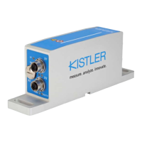
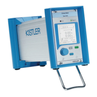
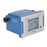
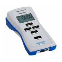
- Charge Amplifiers: Convert electric charges (pC) from the dynamometer into proportional voltages for display, recording, or processing.
- Range Selection: Sensitivities for Fx, Fy, and Fz are set on charge amplifiers (e.g., Type 5080A) to adjust output voltage to the selected scale (N/V).
- Measuring Small Changes in Force: The piezoelectric method allows accurate measurement of small force changes even with a high initial load. For example, fluctuations of 1 N superimposed on a 20 000 N force can be measured with a dynamic threshold of about 0.01 N.
- Useful Frequency Range: The upper frequency limit is influenced by the dynamometer's low damped oscillation, allowing frequencies up to about a third of its natural frequency to be resolved without notable errors. The lower frequency limit is defined by charge amplifier drift and insulation quality.
- Piezoelectric Force Measurement: Accuracy is influenced by sensor and charge amplifier errors, temperature, and environmental factors. A typical measuring chain has a probable error of 1–2% FS. Electrical drift is about ±0.05 pC/s, which can cause the zero point to wander over longer measuring times.
- Tips for Better Measuring Results:
- Store measuring instruments in a room where measurements are taken.
- Keep cables connected to the sensor if possible.
- Install the sensor precisely.
- Warm up the charge amplifier for at least an hour.
- Set the sensitivity value on the charge amplifier to the calibration value.
- For force measurements, work with the .
- Choose the measuring range so that the maximum measurement signal falls between 5 and 10 V.
- For normal force measurements, filter the input signal at 1/3 of the resonance frequency of the measurement setup.
- Only switch the charge amplifier to immediately before measurement.
- Avoid changes in temperature during measurement.
Maintenance Features:
- General: The Type 9139AA is a reliable instrument requiring virtually no maintenance.
- Re-calibration: Re-calibration is necessary after an uncontrolled load. Kistler recommends re-calibration every two years and should be performed by Kistler customer service.
- Maintenance Work:
- Always check for obvious damage before use; do not operate if damaged.
- All repairs (e.g., replacing damaged plug connections or faulty sensors) must be performed by the manufacturer.
- The base and top surfaces are parallel-ground within close tolerances and should not be reworked. Visible scratches can be leveled with a honing stone.
- Regularly clean the vacant nine-pin dynamometer plug connection or the connecting cable with a cleaning agent like Kistler Type 1003 cleaning and insulating spray or pure benzine.
- Fault Elimination: A troubleshooting guide is provided for common issues like no measurement signal, faulty charge amplifier, faulty dynamometer, quasistatic measurement drift, charge amplifier reaching its limits, and "chatter marks" on the machined workpiece. If the dynamometer is faulty, contact Kistler customer service, send the device in its original packaging with a detailed description of the fault and measuring process, and Kistler will repair and re-calibrate it.