- 24 -
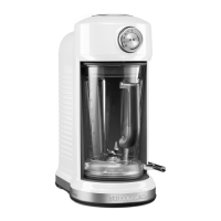
Fig. 58) Reinstall the jar bumper from the inside of the front
plastic housing by turning out counter-clockwise
61. Mount the safety interlock switches on the upper
cover and secure with the (4) 6-32 x .250 screws
(Fig. 59).
Fig. 59) secure the (4) screws that hold safety interlock
switches into place
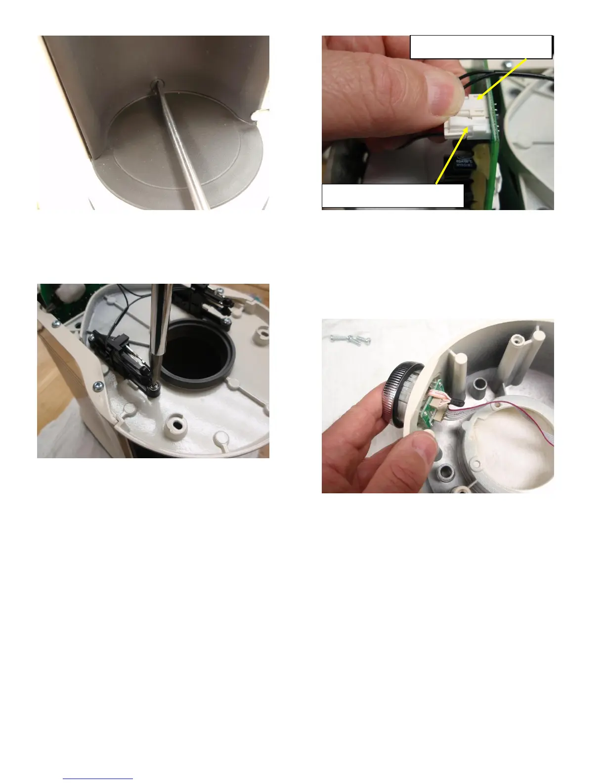
62. Plug the speaker wire harness into the electronic
control circuit board. Plug the safety interlock switch
harness in next to the speaker wire harness (Fig.
60).
Fig. 60) plug the speaker and safety interlock switch wire
harnesses into the electronic control circuit board
Upper Housing Reassembly
63. Snap the UI control into place in the front of the
upper housing. This is most easily accomplished by
inserting the UI straight in and pressing until it snaps
in over the (plastic) retaining tabs (Fig. 61).
Fig. 61) Snap the UI into place in the upper housing
64. Place the collar back into the top of the upper
housing making sure to line it up the keyed slot in
the cover. Secure it to the upper housing with the (3)
8-16 x .562 screws removed in step 7 (Fig. 62).
Safety Interlock Switch plug
Speaker wire harness plug