29
ۣૐ ۞ইૐҴૐ ೠҴসӏѺ ಿ҃మ
6. Installation
6.1 Flue System Connection
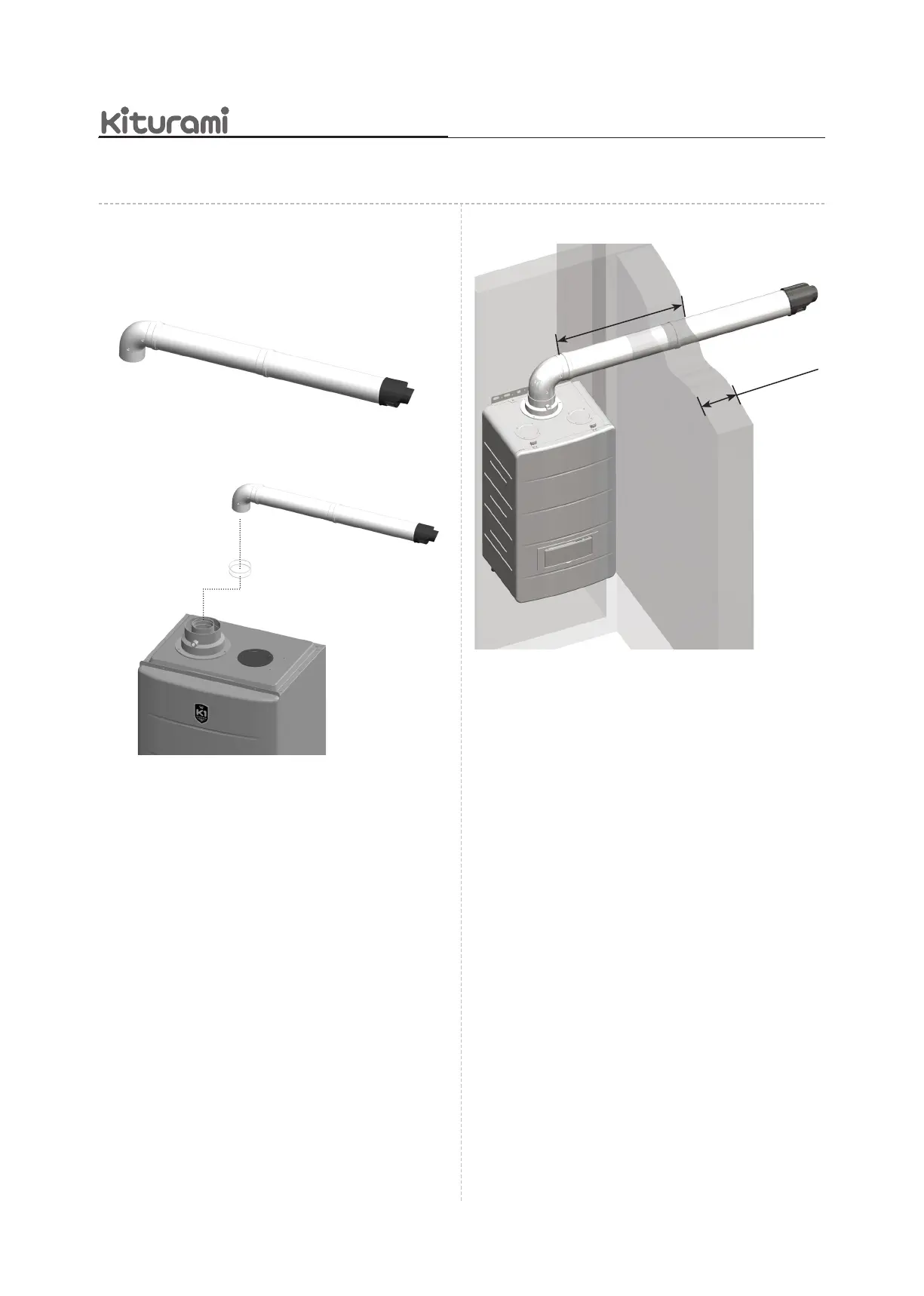
▪HORIZONTALFLUE(ConcentricØ60/Ø100)
▪Ingenerally,theterminalassemblylengthis850mmand
theelbowissupplied.
▪O-ringsshouldbeinsertedtothetopcollaroftheboiler
beforetheelbowconnectstotheboiler.
▪Theterminallengthcanbeadjustedwhenmeasuredfrom
theueelbow850mm(thereis40mmengagementintothe
elbow).
Ifnecessarytoextendoverstandard850mm,canbeadd
theextendueasstandardlength500mmor1,000mm.
▪Locatetheueelbowontheadaptoratthetopoftheboiler.
(Theueelbowforcondensingboilerisangledat93°to
ensureafallbacktotheboiler.)
▪Measurethedistance"X"fromtheoutsidewallfacetothe
elbow.
▪Ininstanceswherethedimensionisunder810mmitwillbe
necessarytoshortentheterminalassemblybycarefulcutting
toaccommodatewallsofthesethicknesses.
O-ringsforsealingof
uecollar
▪Usingtheclearanceholesintheconnectionassemblysecure
ittotheterminalassemblyusingthescrewssuppliedwiththe
ueextendedue.
6.2 Electrical Connection
▪Improperlyconnectingtheelectricalsuppliescanresult
inelectricalshockandelectrocution.Followallapplicable
electricalcodesofthelocalauthorityhavingjurisdiction.
Connectingtheelectricalcomponentsshouldbeperformed
onlybyalicensedprofessional.
6.2.1PowerCableConnection
▪Theboilerelectricalconnectionsmustbemadeby
sufcientlyqualiedstaffinstrictcompliancewiththe
sectionsbelowandwithanyelectricalsafetyregulations
applicableatthetimeofinstallation.
▪Thisboilercomespre-ttedwith1.8mofmainscable.
Thismustbeconnectedtoapermanentlivesupply.
Ifthesupplycordisdamaged,itmustbereplacedby
themanufacturer,serviceagentorsimilarlyqualied
personsinordertoavoidhazard.Shouldbefollowedbelow
process,
X
WallThickness