3-4 Checking the CO2
① The combustion may be checked after running the boiler for several minutes.
To do this it is necessary to set the boiler to Calibration Mode.
② Ensure that all external controls are calling for heating with maximum output.
③ The appliance should be check visually for obvious defects.
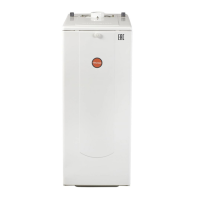
④ There are two test points in the flue, one for flue gas and the other for air.
⑤ Open the air and flue gas test points.
⑥ Insert the flue gas analyzer probe as far as the retainer.
⑦ Allow the boiler to reach thermal equilibrium (around 5~10min)
⑧ The CO and CO2 values should be check each below 200ppm and 5%.
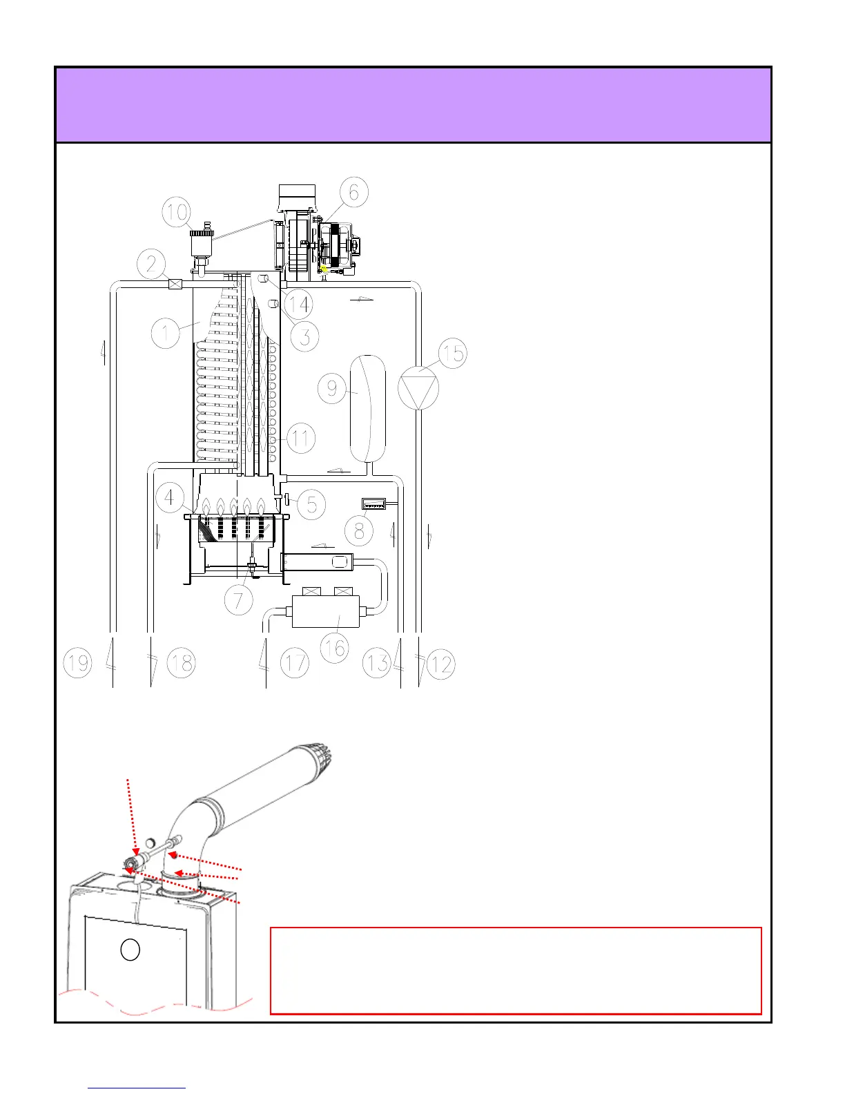
3-3 Water Circuit Diagram
1. Main Heat Exchanger
2. Hot water Limit Switch
3. Heating Temperature Probe
4. Blade Burner
5. Flame Detector(Photo Sensor)
6. Fan
7. Igniter
8. Pressure Gauge
9. Expansion Tank
10. Auto Air-vent
11. DHW Heat Exchanger Coil
12. Heating supply Connection
13. Heating return Connection
14. Heating Water Level Sensor
15. Circulation Pump
16. Gas valve
17. Gas Inlet Connection
18. Hot water Outlet Connection
19. Hot water Inlet Connection
Air inlet test point
Flue gas test point
Exhaust flue
Flue gas analyzer
NOTE : To ensure correct readings the boiler must have reached maximum operating
temperature. . Testing the boiler before thermal equilibrium has been attained will give
incorrect readings.
NOTE : If you have only 1 probe, measure separately air and flue gas, close the test point not
22페이지