15/31
DocumentNo.:KE-4051-00
Controlthesurgegenerationbyusingsurgekiller,sparkkiller,etc.
Connecttheshieldingwiretoearthgroundonthecontrollersidewhenshieldingwireisused.
MakesuretoconnectFGtoearthground.
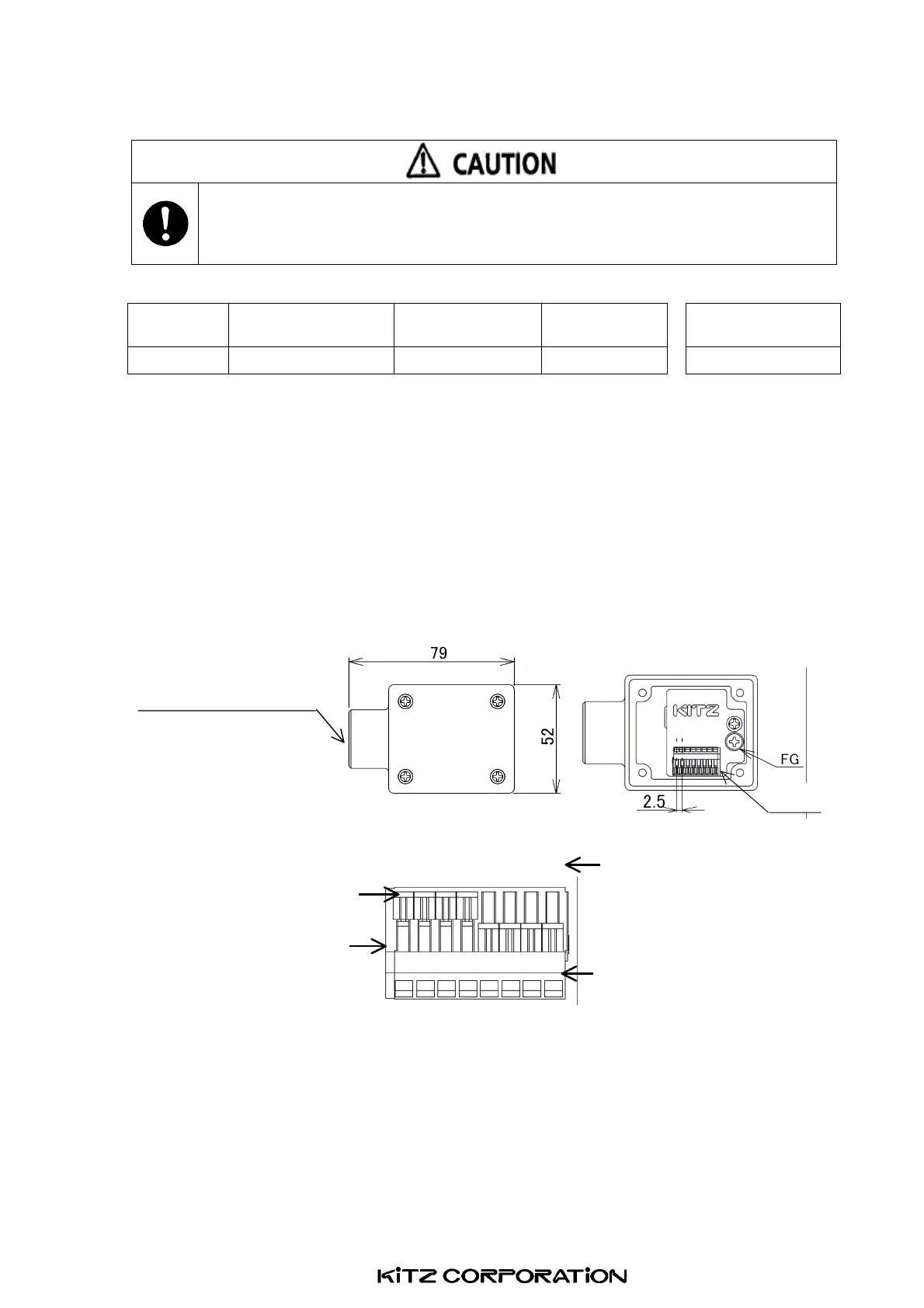
(1)ActuatorCables
Numberof
WireCores
ApplicableElectricWire SolidWire
Flexible
StrandedWire
Exposed Length
8 AWG28toAWG20
0.08to0.5mm
2
0.25mm
2
5to6mm
(2)WiringMethodofTerminalBlock
① Preparethecablesshownin(1)andremovethecoatingofthetipofthecable.
② RefertoFig.16andmovetheclampontheterminalblocktothedirectionwherethewireinsertionport
opens.
③ Insertthecableintothecableinsertionportuntilitreachestheend.
④ Whilekeepingthecableasin ③,movetheclampontheterminalblocktothedirectionwherethecable
insertionportcloses.
⑤ Repeat ① through ④ fortheapplicableterminalblockNo.
*Toopenandclosetheinsertionporteasily,insertthetipofaflat-headscrewdriver(2-3mm)inthedent
ontheclampcenterandslidetheclamp.
(3)SpecificationsofCableLead-InPort
Cableconnectorshallbeapplicabletothecablewithouterdiameterofφ10.5toφ14.5.
ScrewforthicksteelconduitpipeshallbeG16.(PF1/2Bforscrewforthecablelead-inportoftheterminal
box.)
(4) Burnout of the circuit can be prevented by the protection circuit when the power supply is reversely
connectedandenergized.
Fig.16
Cablelead-inport
DetailofTerminalBlock
Terminalblocknumber
(Printedonthesubstrate)
Clamp position where the
wireinsertionportopens.
Cableinsertionport
Clamp position where the wire
insertionportcloses.
12345678
ExternalView
InternalView
Terminalblock
 Loading...