15
OPERATING INSTRUCTIONS
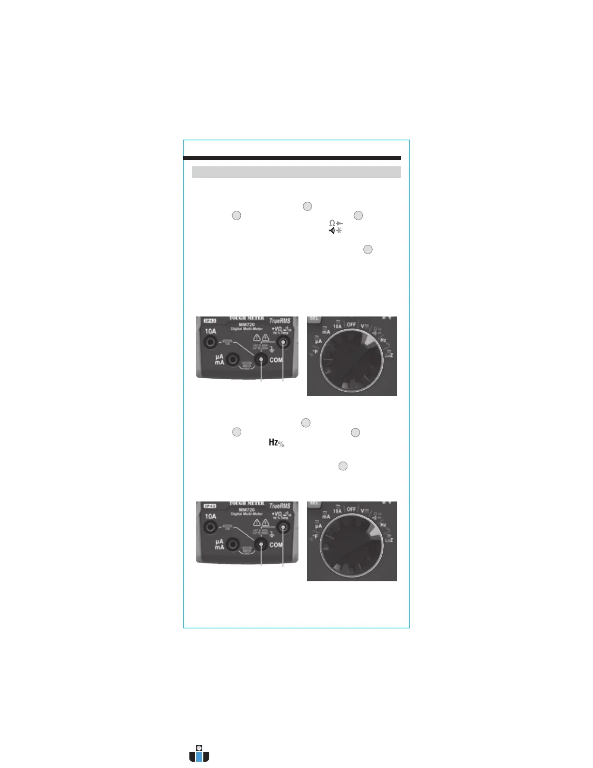
CAPACITANCE
1. Insert RED test lead into VΩ jack
5
, and BLACK test lead into
COM jack
4
, and rotate function selector switch
2
to the
Continuity/Resistance/Diode/Capacitance
setting.
NOTE: The meter defaults to Continuity testing in this mode. To
enter Capacitance testing mode, press the "SEL" button
11
three
times. "nF" or "µF" will appear on the display.
2. Remove power from circuit.
3. Measure capacitance by connecting test leads across the
capacitor. The meter will auto-range to display the measurement
in the most appropriate range.
FREQUENCY / DUTY-CYCLE
1. Insert RED test lead into VΩ jack
5
and BLACK test lead into
COM jack
4
, and rotate function selector switch
2
to the
Frequency/Duty-Cycle
setting.
NOTE: The meter defaults to Frequency testing in this mode. To enter
Duty-Cycle testing mode, press the "SEL" button
11
once. Ensure
that the appropriate icon (either
Hz
or
%
) appears on the display.
2. Measure by connecting test leads across the circuit.
Red leadBlack lead
Red leadBlack lead
www.calcert.com sales@calcert.com1.800.544.2843
0
5
10
15
20
25
30