ELECTRICAL CONNECTION
The electric connection must only be performed by qualified staff, in compliance with all general and
local safety standards.
Check that the power supply voltage and frequency correspond to 220V – 50 Hz.
Product safety is obtained when it is properly connected to an efficient earthing system.
When connecting to the mains power supply, provide a differential magnetic circuit breaker 6 A – Id
30 mA switch with an appropriate breaking load. Electric wiring including grounding must be
performed after removing the mains power supply.
When building the system, remember that cables must be laid in an unmovable way and away from
parts subject to high temperatures. During the final wiring of the circuit, only use components with an
appropriate degree of electrical protection.
KLOVER srl disclaims all liability for damage to people, animals, or property resulting from
failure to properly ground the central heating cooker in compliance with IEC standards.
The electronic control unit manages and controls all the central heating cooker features ensuring
excellent operation of the entire equipment at any time.
Inspection of a possible coupled boiler
If the Smart 120 central heating cooker is to be coupled with a previously installed boiler in the
system (e.g. wall-hung gas boiler), it must be ensured that when the pellet central heating cooker
takes over doing the heating the boiler stops. This is to make sure that you do not have to add up the
heat output in the two appliances installed in the system. This is why our set-up intervenes on the
coupled boiler when the pellet central heating cooker heating pump starts. In this way, there will never
be two boilers operating simultaneously in the same system. The coupled boiler will however always
be used for the production of domestic hot water.
The two wires prepared on the back of the central heating cooker (blue and brown wires) will
have an output voltage of 220 V when the pellet central heating cooker pump is working, and
no voltage when the pump is at a standstill.
Therefore, it is easy to connect the 2 wires to a relay that will control the Room Thermostat inlet of the
coupled boiler.
Control of a possible three-way motorized valve for the DHW system
The Smart 120 central heating cooker is equipped as standard with a control for a possible 3-way
motorized valve to be installed on the domestic hot water circuit. A 4-wire cable with protected faston
connectors 4 wires escapes from the rear part of the central heating cooker, which can be used to
control this valve. The four wires in the cable have different colours, and precisely:
1. Blue wire = COMMON TO 3-WAY VALVE
2. Black wire = PELLET CENTRAL HEATING COOKER SIDE
3. Brown wire = GAS BOILER SIDE
4. Yellow/green wire = GND
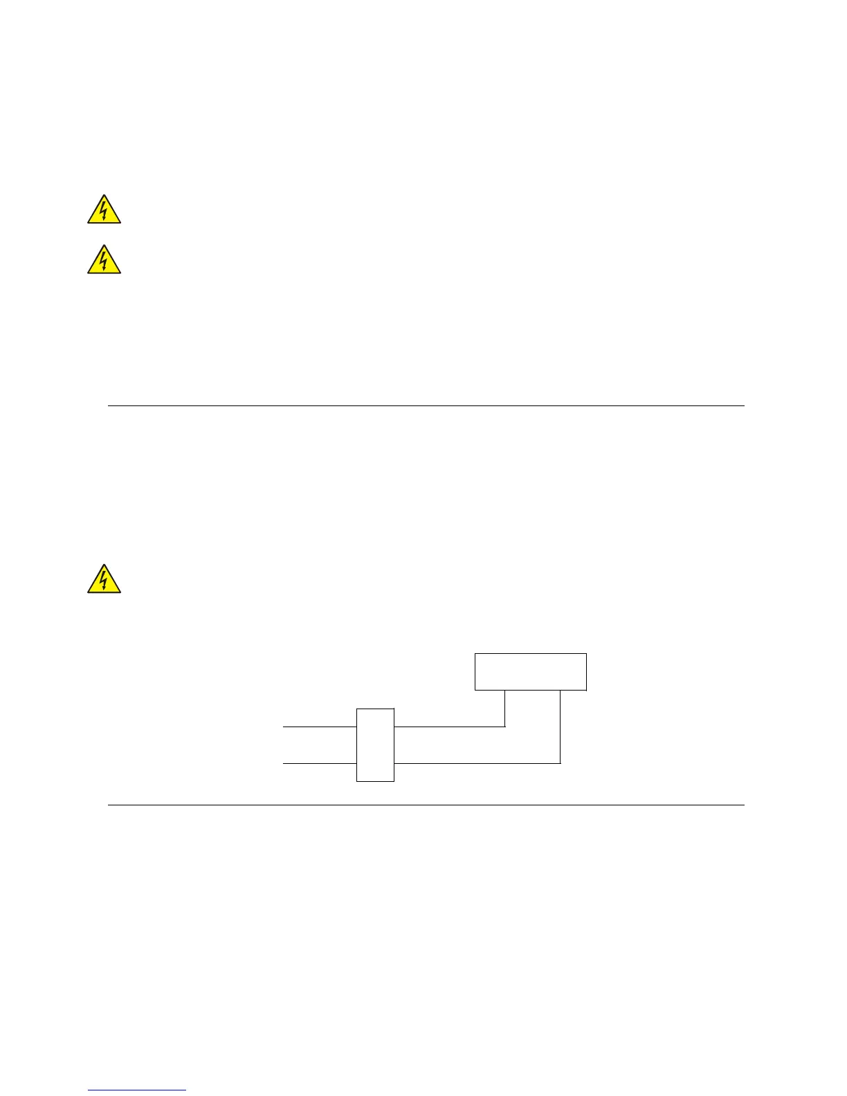
Below find a connection example using a 3-way valve with spring return. Remember that the pipe
connection must be made in a way that when the valve is at rest, the water passes from the gas