PLUMBING CONNECTION
The plumbing connections must be made in a rational way using the connections on the central
heating cooker template. To facilitate the connection of the pipes, we have provided all plumbing
connections on the rear left side, leaving space to easily make the appropriate connections.
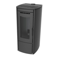
Remove the left side of the central heating cooker to access the “side technical compartment” (see
fig. on p. 10 and 34) to facilitate the plumbing connection.
The central heating cooker can be coupled to any other boiler already installed in the system
including all necessary safety devices and wiretaps according to the system used.
NOTE: The central heating cooker can be installed with a closed expansion vessel equipped
with a device for stopping fuel loading, a safety manual reset thermostat and an audible alarm
activated if temperatures are too high.
The central heating cooker can be installed in the same room as another boiler only if it has a
sealed chamber.
THE CENTRAL HEATING COOKER MUST BE INSTALLED EXCLUSIVELY BY QUALIFIED
ENGINEERS. STRICTLY COMPLY WITH THE INSTRUCTIONS GIVEN IN THIS GUIDE; FOR ANY
DOUBT CONTACT THE TECHNICAL ASSISTANCE CENTRE.
THE MANUFACTURER DISCLAIMS ALL RESPONSIBILITY FOR DAMAGE CAUSED BY
IMPROPER INSTALLATION.
THE NETWORK WATER INLET PRESSURE MUST NEVER EXCEED 3 BAR; RECOMMENDED
WORK PRESSURE: 1.2 BAR.
DO NOT PASS ELECTRIC CABLES IN THE IMMEDIATE VICINITY OF THE FLUE GAS PIPE,
UNLESS THEY ARE INSULATED WITH APPROPRIATE MATERIALS.
IN THE EVENT OF WATER WITH HARDNESS EXCEEDING 28 °f, AN ANTI-LIMESCALE DEVICE
MUST BE INSTALLED. THIS MUST BE SELECTED ON THE BASIS OF WATER
SPECIFICATIONS.



 To Next Page