EasyManua.ls Logo

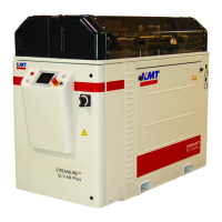
KMT Streamline SL-V 60 Plus User Manual

Default Icon
304 pages
To Next Page IconTo Next Page
Page #1 background imageLoading...
Page #1 background image
MANUAL 20413130(R13)
STREAMLINE SL-V 100 PLUS
WATERJET INTENSIFIER
OPERATION AND MAINTENANCE MANUAL

Table of Contents

Questions and Answers:

KMT Streamline SL-V 60 Plus Specifications

General IconGeneral
TypeWaterjet Cutter
ModelStreamline SL-V 60 Plus
CategoryCutter
Max Cutting CapacityDepends on material
Pump Pressure60, 000 PSI (4137 bar)

Summary

Section 1 Introduction

1.4 Safety

Outlines essential safety precautions and procedures for operating and servicing the equipment.

Section 2 Installation

2.4 Power Requirements

Details electrical codes, voltage, and ampacity requirements for powering the machine.

2.5 Service Connections

Describes the necessary water, drain, and air supply lines for connecting the intensifier.

2.7 High Pressure Piping

Guidelines for installing high pressure piping, including rating, sizing, and material recommendations.

2.8 High Pressure Connections

Procedures for making standard and anti-vibration high pressure connections.

2.9 Commissioning

Procedure for initial startup and testing of the machine after installation.

Section 3 Maintenance

3.2 Maintenance

Emphasizes routine and preventive maintenance for reliable operation and component longevity.

3.3 Maintenance Precautions

Lists critical precautions, including safety device checks and lockout/tagout procedures.

Section 4 Operation

4.2 Startup Sequence

Details the startup procedures based on the previous stop condition and system options.

4.6 Pressure Control Screen

Details the Pressure Control Screen for machines equipped with optional proportional pressure control.

4.10 Run Screen Alarms

Lists alarms displayed on the Run Screen and their indications and comments.

4.11 Alarm Banners

Describes alarm banners that appear during shutdown conditions, listing possible remedies.

Section 5 Low Pressure Water System

5.4 Service and Maintenance Procedures

Details routine servicing and maintenance procedures for the filter, strainer, and booster pump.

Section 6 Recirculation System

6.4 Service and Maintenance Procedures

Outlines routine servicing and maintenance for oil conditioning components.

Section 7 Hydraulic System

7.4 Service and Maintenance Procedures

Covers inspection and maintenance of hydraulic system components like pressure settings and couplings.

Section 8 Electrical System

8.4 Service and Maintenance Procedures

Covers minimal service requirements for electrical components like proximity switches and optical relays.

Section 9 High Pressure Water System

9.5 Service and Maintenance Overview

Provides general guidelines for servicing high pressure water system components.

9.6 High and Low Pressure Water Piping

Details procedures for removing and installing high and low pressure water piping.

9.7 High Pressure Cylinder Assembly

Recommends removing the cylinder assembly for servicing plungers, seals, and pistons.

9.10 High Pressure Seal Assembly

Procedure for replacing the high pressure seal assembly.

9.11 Hydraulic Cartridge Seal and Plunger Removal

Procedure for removing the hydraulic cartridge seal and plunger.

9.15 High Pressure Dump Valve

Provides servicing procedures for 3-port and 2-port high pressure dump valves.

Section 10 Troubleshooting

10.2 Troubleshooting Guide

Provides a guide to diagnose malfunctions, identify symptoms, and find corrective actions.

Section 11 Specifications

11.6 Torque Specifications

Details torque specifications and tightening sequences for high pressure components.

Related product manuals