Simple Maintenance 39
3.5
3.10
3.4
3.12
3.11
3.21
3.13
3.20
3.11a
3.16
3.18
3.19
3.6
3.10a
3.22
3.23
3.24
3.17
3.14
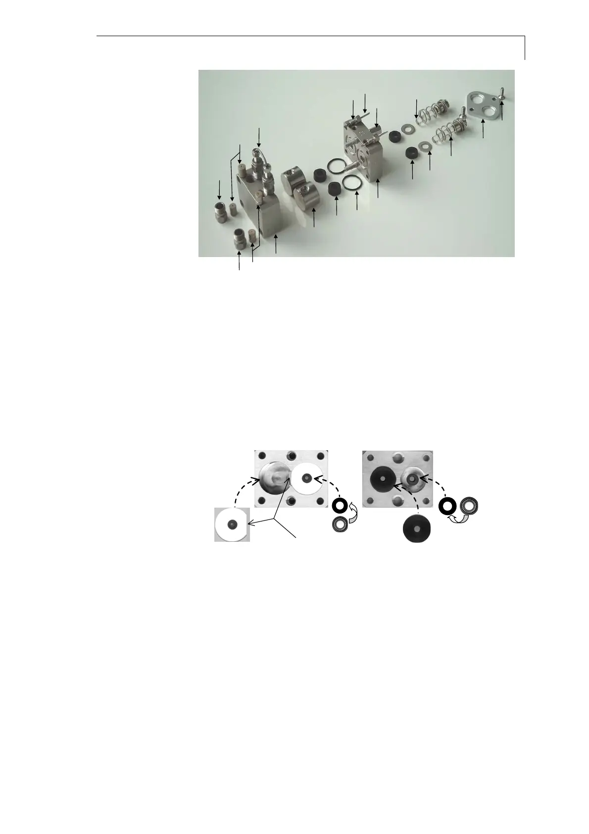
3.3 Pump head screws 3.15 Springs
3.4 Housing 3.17 Piston rod
3.5 Bushing, inlet 3.18 Retaining plate
3.6 Bushing, outlet 3.19 Retaining plate screws
3.10 Check valves, inlet and outlet 3.20 Pressure disc
3.10a Distance holder 3.21 O-ring
3.11 Piston seal, high pressure 3.22 Capillary connection
3.11a Piston seal, low pressure 3.23 Screw connection of backflush
3.12 Seal holder (titanium) 3.24 Capillary of backflush
3.13 Pressure plate
3.14 Spacing bolts
Fig. 30 Explosion view of the pump head
3.4
3.20
3.13
3.12
plane areas
180°
180°
3.11
3.11a
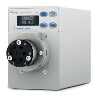
3.4 Housing 3.13 pressure plate
3.11 piston seal 3.11a piston seal
3.12 seal holder 3.20 pressure disc
Fig. 31 Parts of the opened pump head
SOP 30 Assembling the pump head
All position numbers of the items described refer to Fig. 30 and Fig. 31.
1. Always exchange the piston seals (item {3.11} and {3.11a}) after
disassembly of the pump head. Exchange the O-rings (item {3.21})
only if necessary.
2. If you have removed the seal holders from the housing, replace
them very carefully with the plane sides facing each other.
Otherwise the seal holders cannot be replaced without damaging
them.