Installation and connection Diaphragm pump N85, N86
22 Translation of original Operating and Installation Instructions, english, KNF 121258-121528 01/20
To ensure interference suppression according to DIN EN 55014-1
+ A1 and DIN EN 61000-6-3 + A1 pump types equipped with the
brushless DC motor (DC-B) must be equipped with a supplemental
electronic circuit.
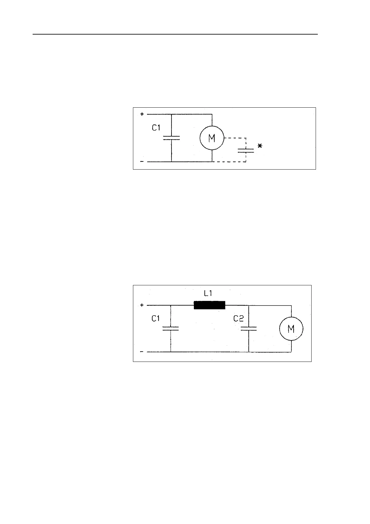
The supplemental circuit must be structured according to the fol-
lowing electrical diagram with the capacitor C
1
:
C1 Capacitor 1
(470 µF, 35V)
Motor
Capacitor in the motor
Fig. 1: Supplemental electronic circuit N 86 K_DC-B with “K” marking on
the type plate
To ensure interference suppression according to DIN EN 55014-1
+ A1 pump types equipped with the brushless DC motor (DC-B)
(without “K” marking on the type plate of the motor) must be
equipped with a supplemental electronic circuit.
The supplemental circuitry is not necessary if a voltage supply has
a suppression of > 20 dB at 150 kHz and 0 dB at 1 MHz.
The supplemental circuit must be structured according to the fol-
lowing electrical diagram and the components defined therein in
order to achieve the required level of suppression.
Capacitor 2 (1000 µF)
Choke coil (6 µH)
Motor
Fig. 2: Supplemental electronic circuit N 86 K_DC-B without “K” marking
on the type plate
For pumps with brushless DC motor without “K” marking on the
type plate the following harmonized standards are met:
DIN EN 55014-1
DIN EN 61000-6-2
Installation