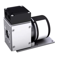
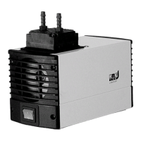
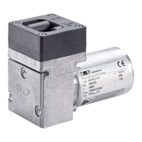
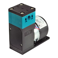
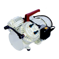
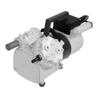
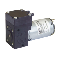
Diaphragm pump N85, N86 Installation and connection
Translation of original Operating and Installation Instructions, english, KNF 121258-121528 01/20 23
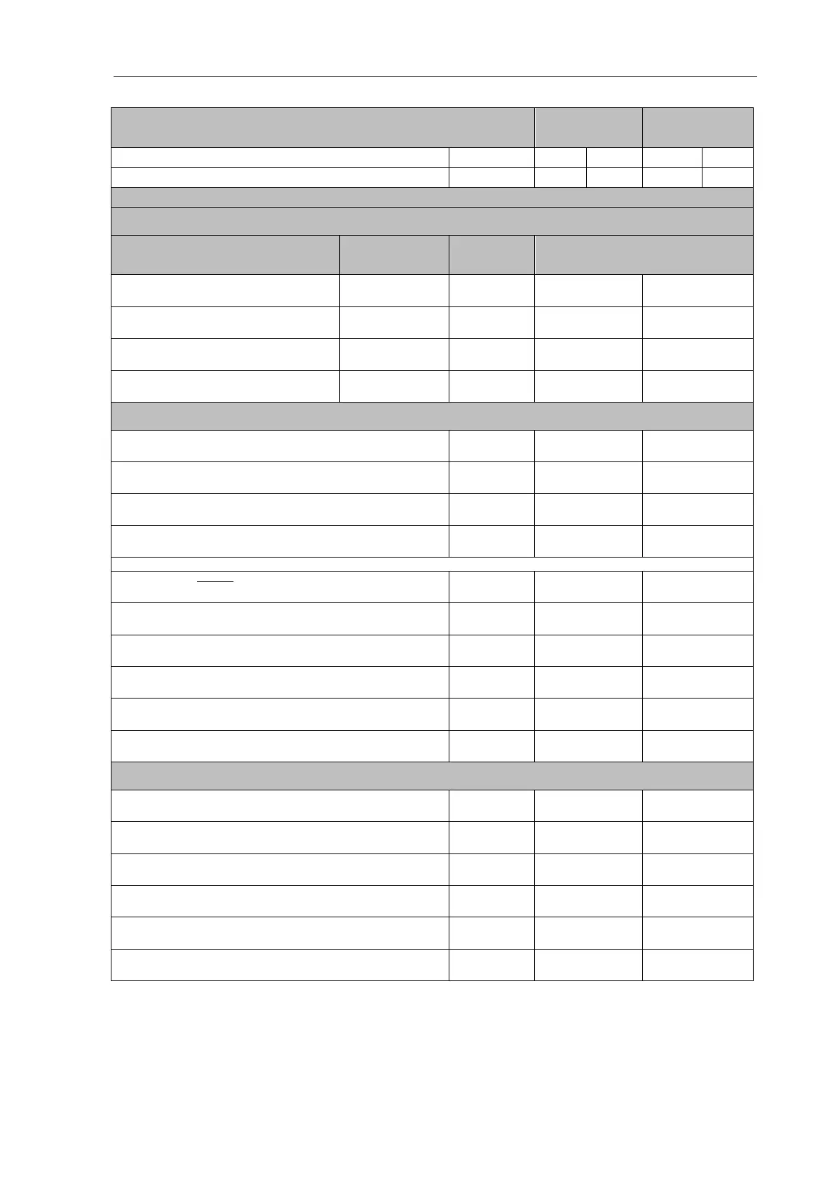
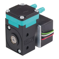
Motor
2-Litzen
(Standard)
4- Litzen
(optional)
Nennspannung / Nominal voltage [V] 12 24 12 24
Spannungsbereich / Voltage range [V] 10…15 14…28 10…15 14…28
Elektrische Anschlüsse / Electrical connection
Litzenbelegung / lead assignment
Funktion / function
Litzenfarbe
lead color
Signalname
signal name
Größe / Size
+ Speisespannung
+ Supply voltage
rot / red + V
S
AWG 24
UL 1007
AWG 24
UL 1007
- Speisespannung
- Ground (0V)
blau oder schwarz
blue or black
- V
S
/ GND
AWG 24
UL 1007
AWG 24
UL 1007
Drehzahlregelung Eingangssignal
Speed control voltage input signal
weiß / white V
Ctrl
-
AWG 24
UL 1007
Drehzahlausgang
Tach output
grün / green V
TCH
-
AWG 24
UL 1007
Drehzahlregelung Eingangssignal V
Crtl
/ Speed control voltage input signal V
Crtl
Steuerspannungsbereich DC
Control voltage range DC
[V] 1.0…4.7
Max. Eingangsspannung
Max. input voltage
[V] ±30
Schwellenspannung
Treshold voltage
[V] 1.0±0.2
Eingangswiderstand (V
Ctrl
< 5V)
Input resistance (V
Ctrl
< 5V)
[kΩ] ≥. 10
PWM Frequenzbereich
PWM frequence
[kHz] ≥ 6
Eingangspegel „high“
Input level „high”
[V] 5
Eingangsspegel „low“
Input level „low“
[V]
0
[0…0.1]
Tastgradbereich
Duty cycle range
[%] ≤ 12 – ≥ 70
Tastgradbeschreibung min. → Motor Aus (ohne Last)
Duty cycle desciption min. → Motor stop (without load)
[%] ≤ 12
Tastgradbeschreibung max. → Motor max Drehzahl (o Last)
Duty cycle desciption max. → Full speed (without load)
[%] ≥ 70
Drehzahlregelung Ausgangssignal V
Tch
/ Speed control voltage output signal V
Tch
Impulse pro Umdrehung
Pulses per revolution
[-] 6
Puls Tastverhältnis
Pulse duty cycle
[%] 33
Ausgangspegel „high“
Output level „high“
[V]
5
[4.2…5.4]
Ausgangspegel „low“
Output level „low“
[V]
0
[0…0.6]
Max. Strombelastbarkeit
Max current carrying capacity
[mA] 0.1
Output series resistance
[kΩ] 3.9
Tab. 15: Connection plan motor electronics for pumps with brushless DC
motor