Installation and connection Diaphragm pump N85, N86
24 Translation of original Operating and Installation Instructions, english, KNF 121258-121528 01/20
7.3. Pneumatic connection
CAUTION
Personal injury or damages to property by ejected
protective
plugs
protective plug at the pressure side of the
pump hasn’t been removed, it could be ejected be-
cause of the overpressure during operation.
Remove the protective plug during the installa-
tion.
Only connect components to the pump which are designed for
the pneumatic data of the pump (see Chapter 4, Technical Da-
ta).
Protect the pump with a pressure relief device between the
pressure connection of the pump and the first shut-off valve.
If the pump s used as a vacuum pump, safely discharge the
pump exhaust at the pump’s pneumatic outlet.
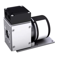
Connecting pump
A marking on the pump head shows the direction of flow.
Confusion between suction and pressure sides can lead to
breakage of
connected components on the suction and pres-
1. Remove the protective plugs from the hose connection
threads.
2. The accessories silencer, filter, and hose connectors (where
applicable) are screwed into the port threads.
Mount the silencer at the pressure side if necessary.
3. Connect the suction line and pressure line (see Chapter 4,
Tab. 13 for mounting dimensions).
4. Lay the suction and pressure line at a downward angle to pre-
vent condensate from running into the pump.
components