Diaphragm pump N85, N86 Servicing
Translation of original Operating and Installation Instructions, english, KNF 121258-121528 01/20 29
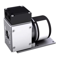
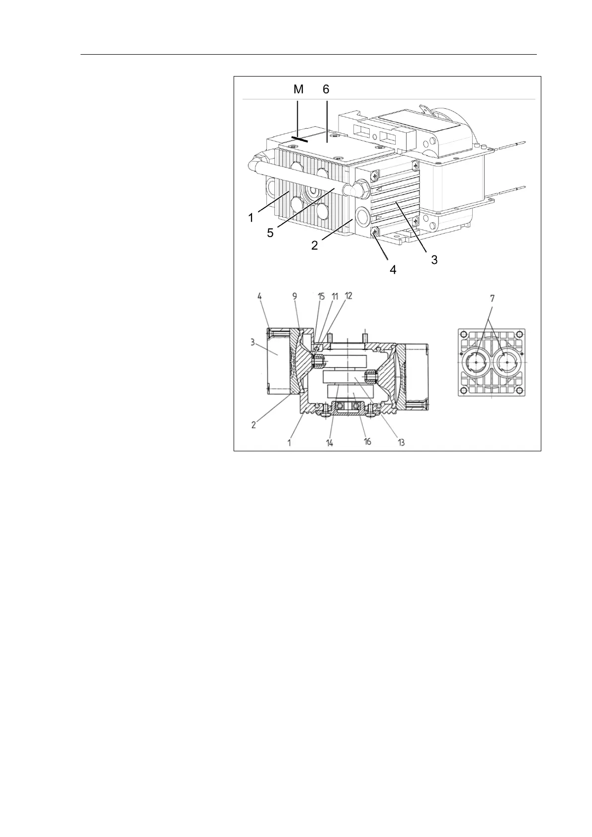
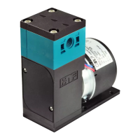
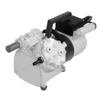
Fig. 12: Two-headed pump (N85.3K_E)
The position numbers in the following text refer to Fig. 12. Proceed
as follows:
a.) Preparatory steps
1. Remove the pump from the source of electrical power. Make
sure the pump is voltage-free and secure it.
2. Only for models with DC motors (no cooling fan): Remove cov-
er (6) from pump housing after loosening the four screws.
On these models, which have no fan, where reference is made
to turning or holding the cooling fan, the necessary operations
must be carried out by turning or holding the counterweight
(16).
b) Removing the pump head
1. Mark the position of the head plate (3), intermediate plate (2),
and housing (1) relative to each other by a drawing line with a
felt-tip marker (M). This helps avoid incorrect assembly later.
2. Remove the pneumatic connection (5) by pulling the tubing
from the connectors.
3. Undo the 4 screws (4) in the head plate and lift the head plate
(3) with the intermediate plate (2) off the pump housing.
2 Intermediate plate
3 Head plate
4 Screw
5 Connection
6 Cover
7 Valve plate/sealing
8
9 Diaphragm
10
11 Diaphragm spacer(s)
12 Disk spring(s)
13 Connection Rod
14 Eccentric
15 Washer
16 Counter weight