THEORY GUIDE Optical
10DEC05
TG4825-1
Page
66 of 120
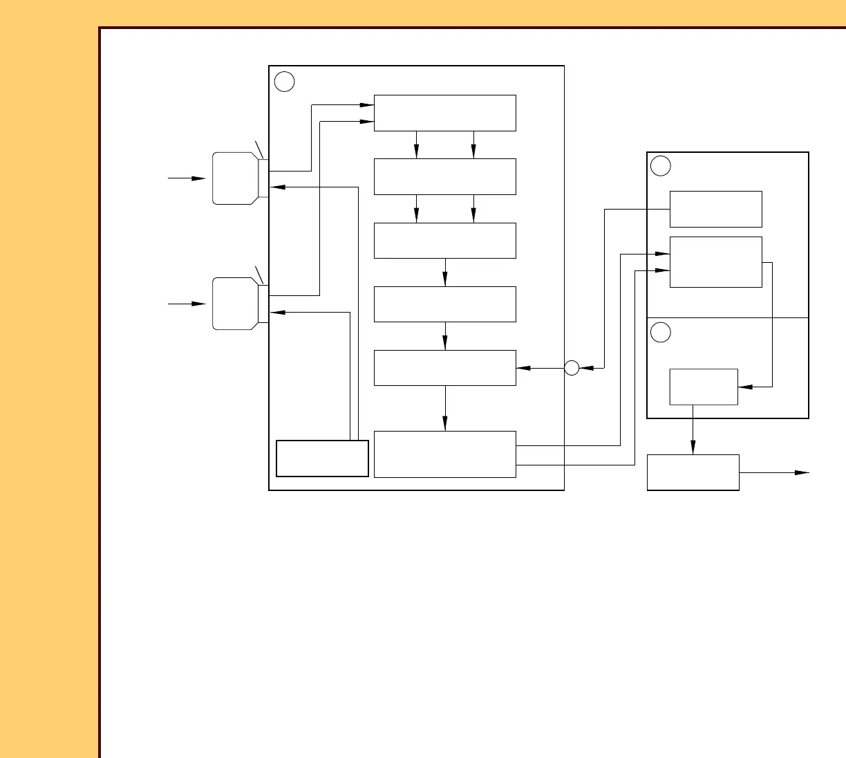
Operation of the PMT/DAS BOARD:
1. The 2 PMTs connect to the PMT/DAS BOARD A5. The HIGH VOLTAGE POWER SUPPLY
feeds power to the HIGH VOLTAGE DIVIDERS. Each PMT has a HIGH VOLTAGE
DIVIDER that sends the given levels of high voltage to the components inside the PMTs.
2. The ANODE of each PMT is connected to a CURRENT-TO-VOLTAGE AMPLIFIER, which
changes the small current signal from each PMT into a corresponding voltage signal.
Each of the voltage signals moves through a PMT GAIN CONTROL D/A CONVERTER.
These CONVERTERS change the signal level from each PMT to adjust for gain variations
from PMT to PMT.
DIVIDERS
2 CURRENT-TO-VOLTAGE
AMPLIFIERS
2 PMT GAIN CONTROL
D/A CONVERTERS
SUMMING AMPLIFIER
LOW PASS FILTER
16-BIT A/D CONVERTER
DATA MULTIPLEXER
PMT1
analog
voltage
signals
ANODE
light
blue
ANODE
light
blue
PMT1
POWER SUPPLY
HIGH VOLTAGE
to HIGH
VOLTAGE
16 bit
PMT/DAS BOARD
A5
PIXEL CLOCK
FIFO BUFFER
DIGITIZER BOARD
A3
MCPU BOARD
A2
BUFFER
8 bit
8 bit
raw image
data
digital
image
data
INTERNAL PC
images
processed
digital
to network
H194_5046HC
 Loading...


