28 Installation TP-5977 7/98
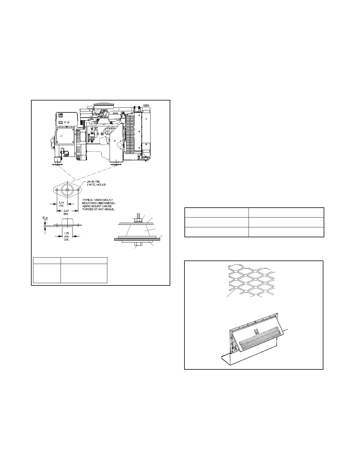
6.2 Mounting
Securely fasten the generator set to avoid unwanted
movement from vibration and road shock. Attach the
generator set vibromounts directly to the vehicle’s
frame. See Figure 6-1 for vibromount installation.
Vibromounts
Attachthevibromountstothegeneratorsetas shownin
Figure 6-1 using the supplied hardware.
560567
Purple Engine left side
White (2) Generator end
Blue Engine right side
Color Mounting Location
1
2
3
4
5
6
7
1. Lock nut
2. Flat washer 7/16 x 1
3. Generator set frame
4. Vibromount
5. Vehicle frame
6. Flat washer 13/32 x 2
7. Screw 3/8-16 x 2-1/4
Figure 6-1. Vibromount Installation
6.3 Cooling System
See Section3—CoolingSystem for adescription of the
generator sets cooling system.
Air Requirements
High water temperature shutdown switch. Each
generator set includes a high water temperature
shutdown switch which automatically shuts down the
generator set if operating temperatures climb too high.
To prevent generator set shutdown, ensure
adequately-sized compartment openings to allow
circulation of the cooling and combustion air.
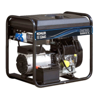
Free-air opening. Figure 6-2 shows thegenerator set
coolingrequirements. Louvers,screens,andprotective
grill work restrict air flow. Even a simple, open mesh
screen, as shown in Figure 6-3, restricts air flow as
much as 45%. Increase the intake openings to
compensate for restrictions.
Sealtheair-inlet openings,at theengineradiatorand/or
generatorendbracket, against thecompartmentwallto
ensure that only exterior air is drawn into the generator
compartment.
Model Air Requirements
10/12CCE/CEZ (60 Hz) 2400 (68)
10/12CCE/CEZ (50 Hz) 2000 (57)
Figure 6-2. Engine/Generator Cooling
Requirements—cfm (m#/min.)
560567
1
1. Wide mesh screen
Figure 6-3. Inlet Screen