TP-5977 7/98 Installation 33
Circuit
Breaker
Gen.
N
L0L2L1
9
3
5
11
1
7
4 6
2
10
12
8
Circuit
Breaker
Gen.
N
L0L3L1
1
L2
7
2
8
3
9
6
10
4
11
5
12
Circuit
Breaker
Gen.
N
L0L3L1 L2
10
11
12
1
2 3
9
6
8
5
4
7
Circuit
Breaker
Gen.
N
L0L3L1 L2
12
2
6
5
7
4
8
9
1
10
3
11
Circuit
Breaker
Gen.
N
L0L3L1 L2
1
7
2
8
3
9
6
10
4
11
5
12
110/220V.
120/240V.
1 , 3 Wire
138/240V.
3 , 3 Wire
220/380V.
240/416V.
277/480V.
3 , 4 Wire
110/220V.
120/240V.
3 , 4 Wire
110/190V.
120/208V.
3 , 4 Wire
Gen.
Circuit
Breaker
N
L0
4
1
3
2
L1
L2
120/240V.
110/220V.
115/230V.
1 , 3 Wire
/
L2
Gen.
Circuit
Breaker
N
L0
4 2
3
1
L1
120V.
110V.
1 , 3 Wire
0
/
0
/
0
/0
/
0
/
0
/
0
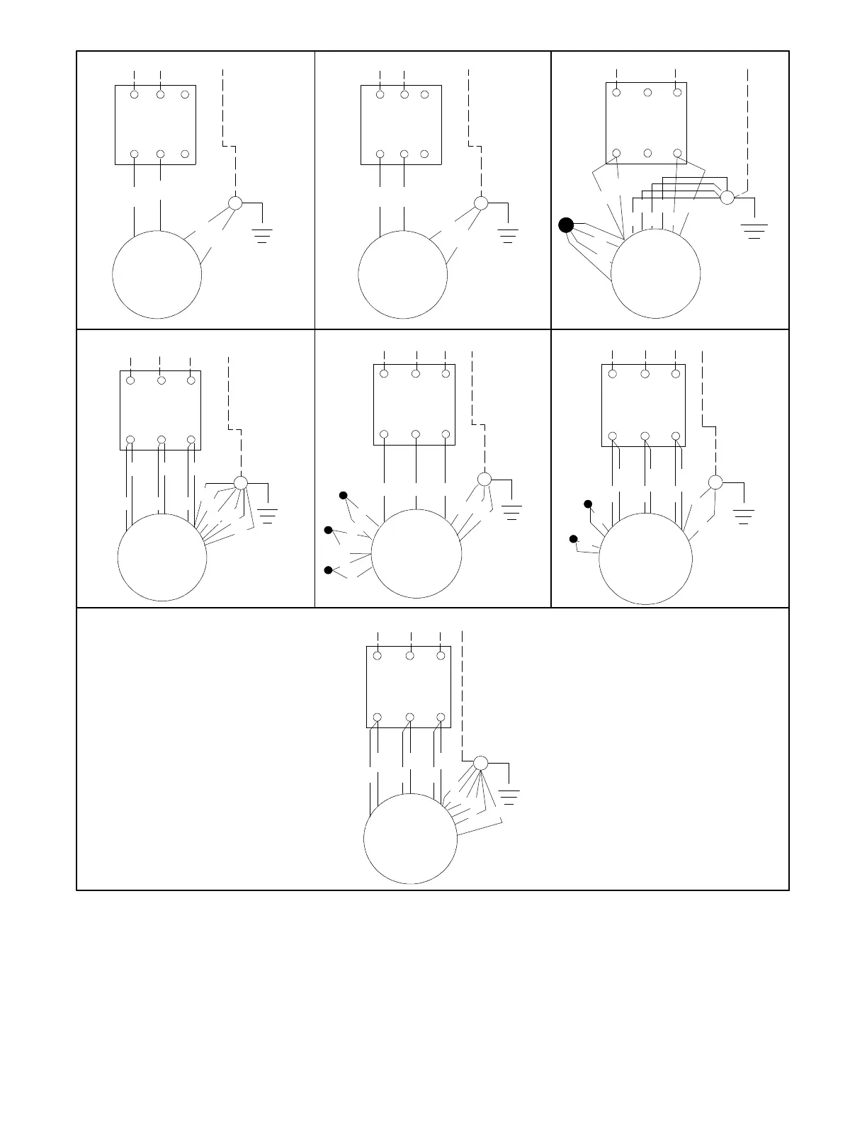
Figure 6-6. Circuit Breaker Connections
6.6.3 Remote Switch Connection
Controllers include an accessory plug (P3) for easy
connection of the remote switch. One end of the 15 in.
(381 mm) P3 wiring harness plugs directly into the
controller. The pigtailleads on the remaining end of the
harness connect to the appropriate remote panel
terminals via customer-supplied wiring. Connect the
remoteoperatingcontrolstothecorrectP3wireharness
lead. See the wiringdiagrams inthe Section5—Wiring
Diagrams for identification of P3 harness leads.