TP-6196 10/09104 Section 7 Disassembly/Reassembly
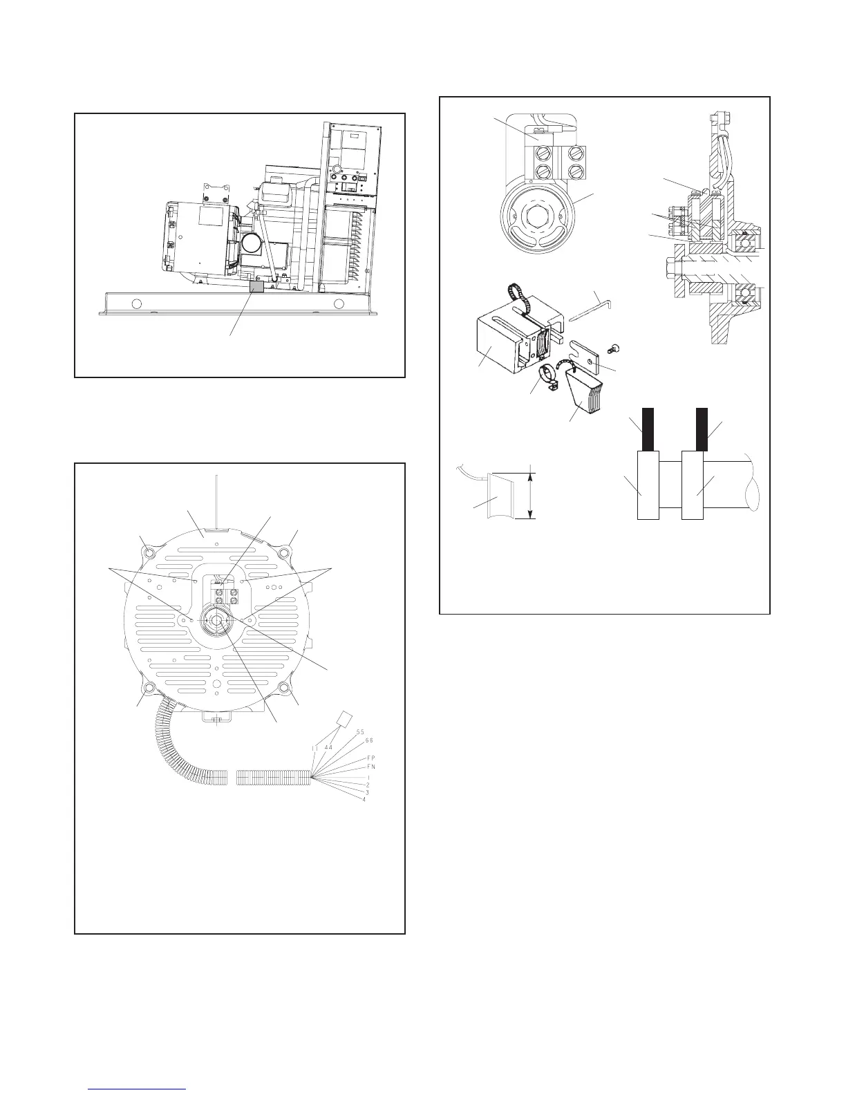
b. Raise the alternator end of the generator set
enough to place a thin block of wood beneath
the rear of the engine. See Figure 7-9.
GM29253A
1
1. Engine support block
Figure 7-9 Generator Set, Right Side
c. Remove 4 screws securing the brush cover to
the alternator end bracket. See Figure 7-10.
GM29253B-P
5
6
2
4
2
2
2
1
1
1. Brush cover screws
2. Overbolt and centering washer
3. Alternator end bracket
4. Brush holder
5. Brush retainer wire hole
6. Thrubolt
3
Figure 7-10 Alternator End Bracket
d. Raise the brushes in the brush holder and
insert a small piece of wire into the brush holder
retainer wire hole. See Figure 7-10 and
Figure 7-11.
TP5867
1
2
3
Front View
Side View
1
2
3
New 1.9 cm (0.75 in.)
4
5
6
1
7
8
2
2
3
1. Brush holder
2. Slip ring
3. Brush(es)
4. Retainer wire
5. Shim
6. Spring
7. Correctly positioned brush
8. Incorrectly positioned brush
GM29253B-P
Figure 7-11 Brush Details
e. Remove the alternator overbolts and centering
washers. See Figure 7-10.
f. Using a soft-faced hammer, strike the side of
the end bracket with medium-force blows to
remove the end bracket from the stator or
remove the end bracket from the stator using a
puller.
g. Remove the leads connected to the end
bracket from the convoluted conduit leading to
controller. Set the end bracket assembly aside.
6. Check the brushes.
a. Remove the brush holder from the end bracket.
See Figure 7-10.
b. Inspect the brushes. Replace brushes when
they are worn to half of their original size. See
Figure 7-11 and Section 6.6, Brushes.

 Loading...


