TP-6398 4/0712 Section 1 Features
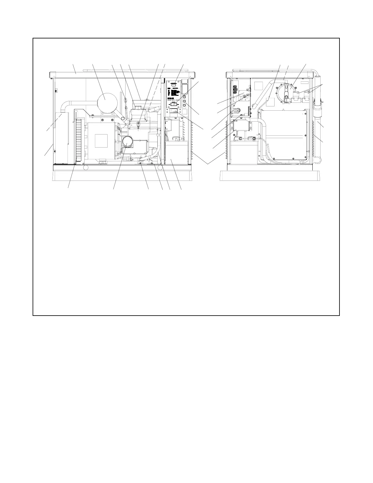
1.5 Generator Set Components
123 658 23
1617
4
13
20
12
19
22
14
10
24
ADV-7023-A
1. Enclosure
2. Silencer
3. Oil check
4. Oil fill
5. Air cleaner
6. Spark plug locations (both sides)
7. Carburetor heater location (under air cleaner; if equipped)
8. Controller LED display
9. Generator set master switch (RUN\OFF/RESET\AUTO)
10. Fuses
11. Line circuit breaker
12. Air intake vents
13. Engine starting battery location
14. Oil drain hose
15. Nameplate (on base)
16. Oil drain valve
17. Oil filter
18. Alternator cooling air intake
19. Exhaust outlet
20. Spark arrestor
21. DSAM leads
22. LP fuel jet location (not shown)
23. Gas regulator assembly
24. Fuel solenoid valves (2)
25. Wiring kit
26. Battery charger
27. Ground stud (GND)
28. 120VAC receptacle
29. Relay board
11
27
18
9
29
21
26
15
28
25
7
12
Figure 1-1 Generator Set Components

 Loading...


