TP-6398 4/07 25Section 3 Scheduled Maintenance
3.9 Battery Charger
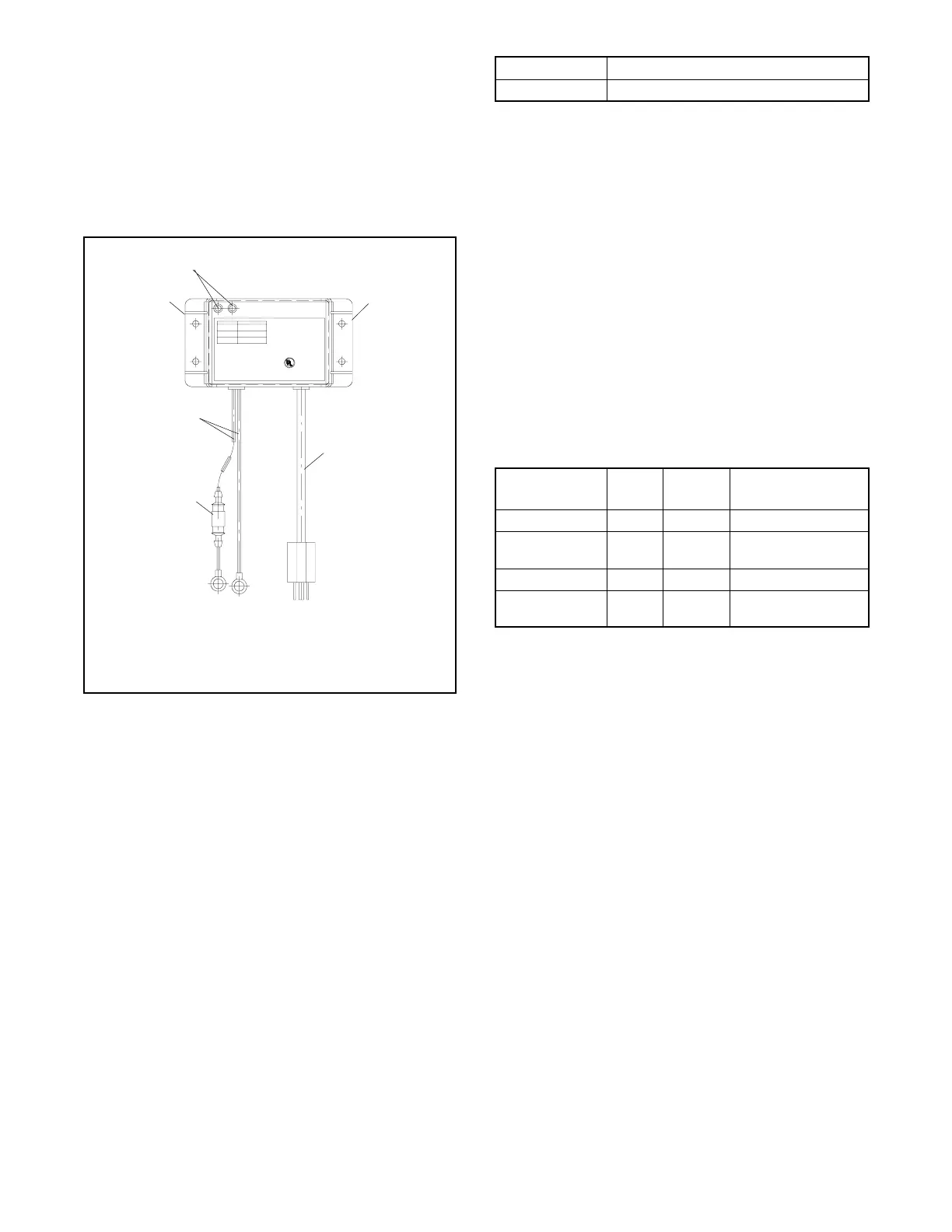
The generator set is equipped with a 6-amp
float/equalize battery charger to maintain the engine
starting battery. The charger’s DC leads are factory-
wired. Figure 3-7 illustrates the battery charger.
Periodically tighten all connections. No other
maintenance on the battery charger is required.
INDICATOR
Red:
Red & Green:
Green:
VOLTS= 11.8--14.0
AMPS= 5.0--6.0
VOLTS= 14.0--14.5
AMPS= 1.5--5.0
VOLTS= 13.0--13.6
AMPS= 0.1--1.5
CAUTION:To r educe the risk of elect rical shock,
connect only to pr operly gr ounded outlet.
Allowable Battery Types: Lead Acid a nd Gel Cell
INPUT: 115 VAC 50/60Hz @ 1.6A
OUTPUT: 12 VDC @ 6 Amps
MAX. BAT.: 180 Amp Hr. Max.
DATE:
6 AMP AUTOMATIC
BATTERY CHARGER
R
C US LISTED
BATTERY C HARGER
53AB
2608KH
1
1. LED indicators
2. Mounting flanges
3. AC power cord
2
5
2
3
4
4. Fuse
5. Battery leads, 12 VDC
Figure 3-7 6-Amp Float/Equalize Battery Charger
3.10 Circuit Protection
If the generator set circuit breaker trips or the fuses blow
repeatedly, see Section 4, Troubleshooting, for possible
causes.
3.10.1 Line Circuit Breaker
A line circuit breaker interrupts the generator output in
the event of a fault in the wiring between the generator
and the load. The line circuit breaker location is shown
in Figure 1-1. See Figure 3-8 for the circuit breaker
ratings. If the circuit breaker trips, reduce the load and
switch the breaker back to the ON position. With the
breaker in the OFF position the generator set runs but
the generator output is disconnected from the load.
Model Circuit Breaker Rating, Amps
12RESM1/RESL 50
Figure 3-8 Line Circuit Breakers
3.10.2 Fuses
Three fuses are located next to the generator set
controller. The fuses are easily accessed from the
service side of the generator set. See Figure 1-1 for the
fuse location.
A 10-amp fuse in the battery charger DC lead protects
the battery charger. See Section 2.5.
Always identify and correct the cause of a blown fuse
before restarting the generator set. Refer to Section 4,
Troubleshooting, for conditions that may indicate a
blown fuse. Replace blown fuses with identical
replacement parts. See Figure 3-9 for fuse ratings and
part numbers.
Fuse Label
Part
Number
Location
Auxiliary winding F1 292937 Lead 55
Relay interface
board
F2 223316 Lead PF2
Controller F3 223316 Lead PF1
Battery charger — AGS 10 Battery charger DC
lead. .
Figure 3-9 Fuses
3.11 Storage Procedure
Perform the following storage procedure before
removing the generator set from service for three
months or longer. Follow the engine manufacturer’s
recommendations for storage, if available.
Note: Run the generator set monthly whenever
possible.
3.11.1 Lubricat ing System
1. Operate the generator set until it reaches operating
temperature, or about 15 minutes.
2. Stop the generator set.
3. While the engine is still warm, drain the engine
lubrication oil from the engine crankcase.

 Loading...


