24 TP-7092 11/22
Figure 18 Carburetor Heater, 18 and20 kW Models
1.8.7 Emergency Stop Kit
An emergency stop button is available as a loose kit. Pressing the emergency stop button causes the generator set to shut down
immediately. The generator controller displays an emergency stop shutdown message after the button is pressed.
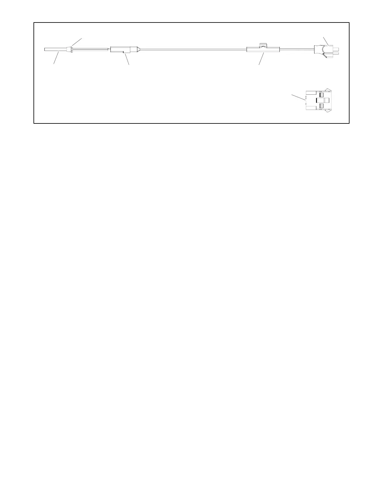
E-stop assembly harness contains the E-stop, contact block, and two leads connected to the contact block. The harness is
factory-assembled. The kit also includes the emergency stop switch decal.
The generator set enclosure is designed with an opening for the emergency stop button. Install the emergency stop button as
described in the TT-1613 and TT-1795 instructions.
RDC2 firmware to version 5.5 or higher is required for E-stop operation. Use a personal computer (laptop) and Kohler
®
SiteTech™ software or the USB Utility to update the controller firmware, if necessary. See TP-6701, SiteTech Operation Manual,
or TT-1636, Firmware Update Using the USB Utility, for instructions if necessary.
1.8.8 Load Management
Two optional load management devices are available for use with single-phase generator sets and a model RXT or RDT transfer
switch.
• The optional Load Shed Kit mounts inside a model RDT or RXT transfer switch.
• The combined interface/ load management board is available for the Model RXT transfer switch.
The load management devices provide an automatic load management system to comply with Section 702.5 of NEC 2008. The
installer is responsible for ensuring that the power system installation complies with all applicable state and local codes.
Note:
The load management devices are only compatible with single-phase generator sets.
The load management device automatically manages up to six residential loads. Two relays are provided to control two
independent air conditioner loads. Up to four power relay modules can be connected for management of non-essential secondary
loads.
The load management device is controlled by theRDC2 controller. The load on the generator set is monitored, and loads are
added or shed in the order of their priority. See the installation instructions provided with the load shed kit or the Model RXT
Operation and Installation Manual for more information.
1.8.9 PowerSync Automatic Paralleling Module (APM)
The PowerSync
®
Automatic Paralleling Module (APM) allows the use of two Model 14RCA or two 20RCA generator sets in a
single-phase paralleling system to supply power to one building or site. The APM is not applicable to the 18RCAL generator set.
See Figure 19.
The APM provides a common connection point for paralleling generators and permits individual control of the generator
connections, allowing for synchronization, redundancy, and generator management.
 Loading...