TP-6773 5/12a14 Section 3 Cooling System
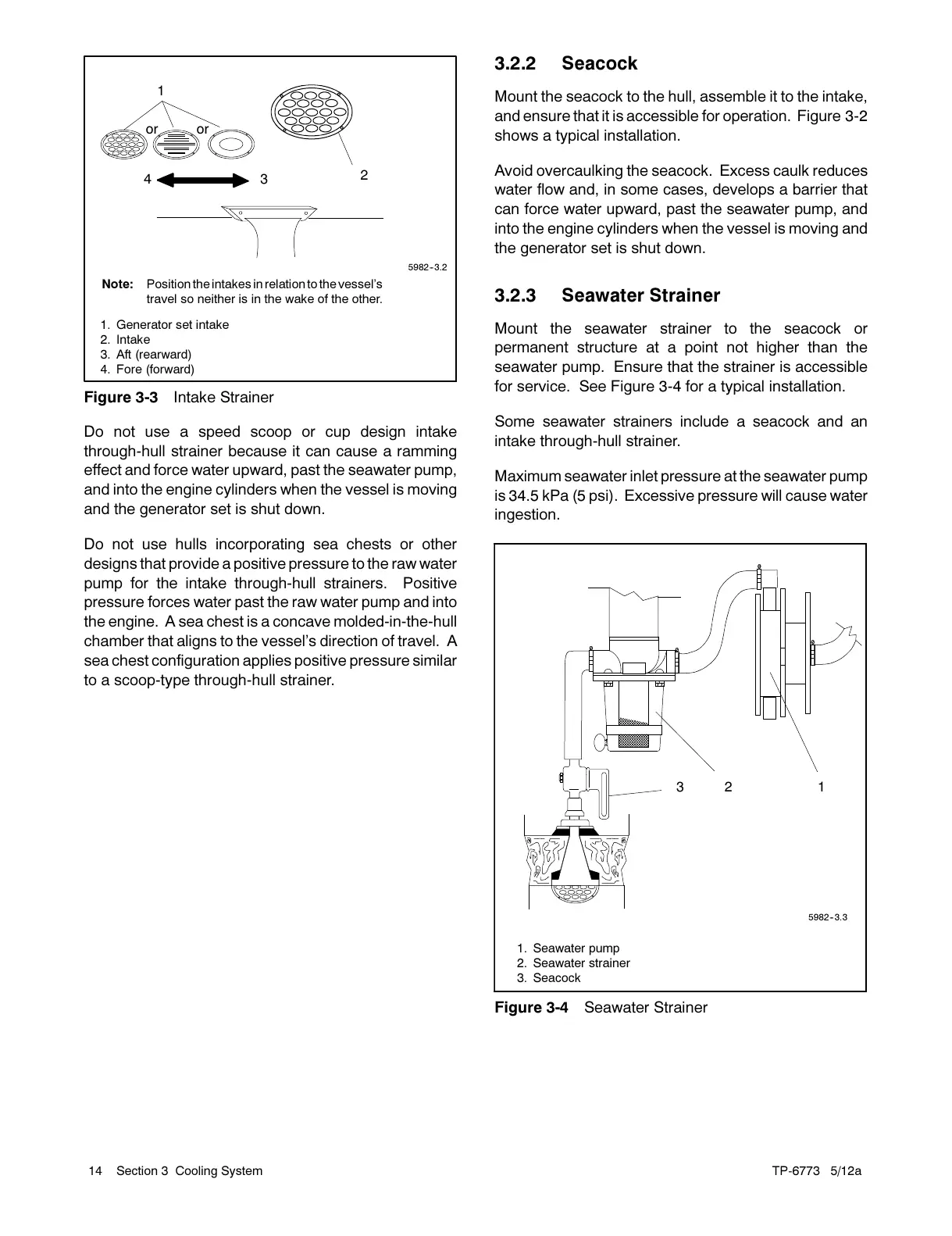
Note: Position the intakes in relationtothevessel’s
travel so neither is in the wake of the other.
1
2
4 3
5982--3.2
1. Generator set intake
2. Intake
3. Aft (rearward)
4. Fore (forward)
or or
Figure 3-3 Intake Strainer
Do not use a speed scoop or cup design intake
through-hull strainer because it can cause a ramming
effect and force water upward, past the seawater pump,
and into the engine cylinders when the vessel is moving
and the generator set is shut down.
Do not use hulls incorporating sea chests or other
designs that provide a positive pressure to the raw water
pump for the intake through-hull strainers. Positive
pressure forces water past the raw water pump and into
the engine. A sea chest is a concave molded-in-the-hull
chamber that aligns to the vessel’s direction of travel. A
sea chest configuration applies positive pressure similar
to a scoop-type through-hull strainer.
3.2.2 Seacock
Mount the seacock to the hull, assemble it to the intake,
and ensure that it is accessible for operation. Figure 3-2
shows a typical installation.
Avoid overcaulking the seacock. Excess caulk reduces
water flow and, in some cases, develops a barrier that
can force water upward, past the seawater pump, and
into the engine cylinders when the vessel is moving and
the generator set is shut down.
3.2.3 Seawater Strainer
Mount the seawater strainer to the seacock or
permanent structure at a point not higher than the
seawater pump. Ensure that the strainer is accessible
for service. See Figure 3-4 for a typical installation.
Some seawater strainers include a s eacock and an
intake through-hull strainer.
Maximum seawater inlet pressure at the seawater pump
is 34.5 kPa (5 psi). Excessive pressure will cause water
ingestion.
123
5982--3.3
1. Seawater pump
2. Seawater strainer
3. Seacock
Figure 3-4 Seawater Strainer

 Loading...


