TP-6773 5/12a46 Section 8 Reconnection
Voltage Reconnection Procedure
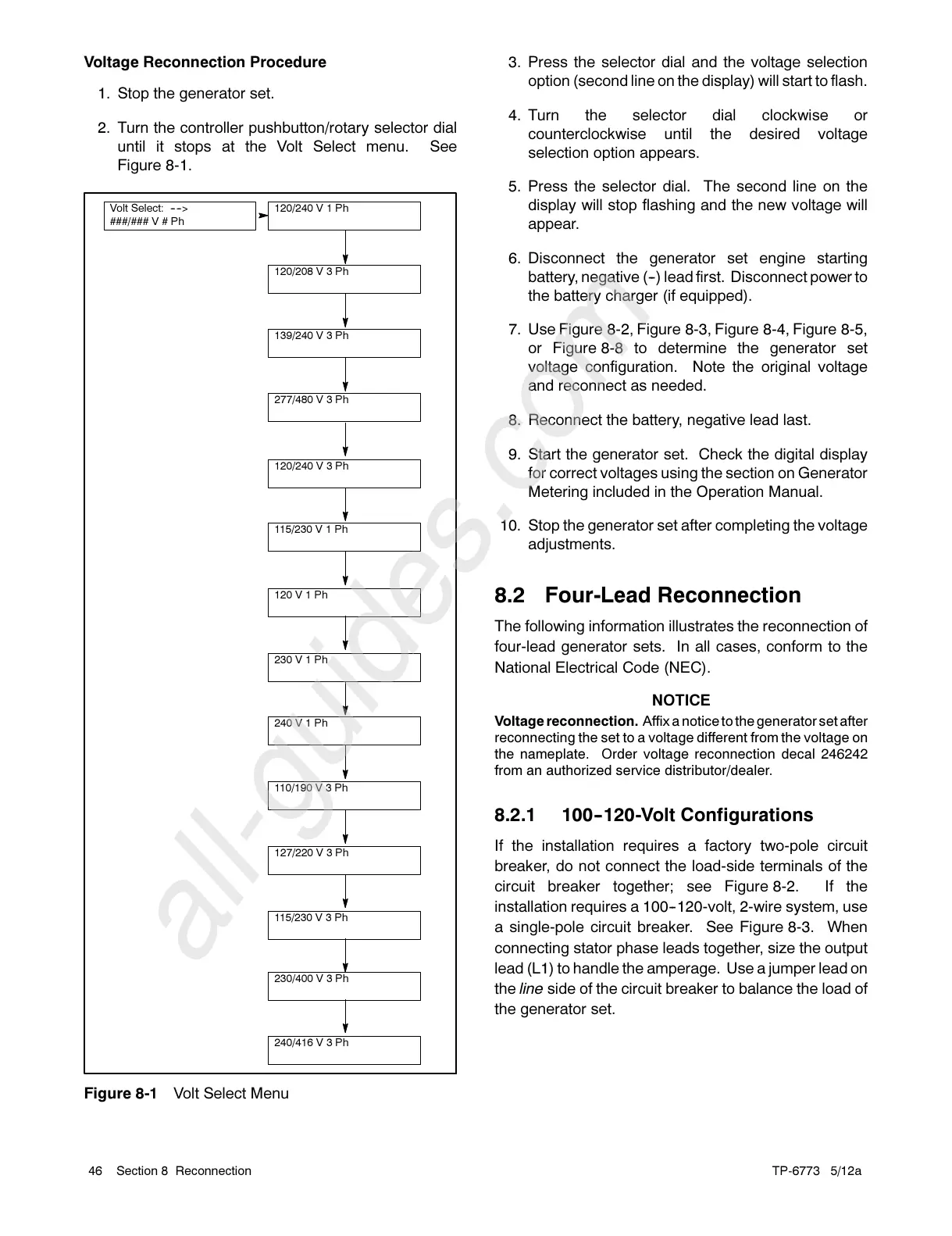
1. Stop the generator set.
2. Turn the controller pushbutton/rotary selector dial
until it stops at the Volt Select menu. See
Figure 8-1.
Volt Select: ---->
###/### V # Ph
120/240 V 1 Ph
115/230 V 1 Ph
120 V 1 Ph
240 V 1 Ph
230 V 1 Ph
120/208 V 3 Ph
120/240 V 3 Ph
127/220 V 3 Ph
139/240 V 3 Ph
277/480 V 3 Ph
110/190 V 3 Ph
230/400 V 3 Ph
240/416 V 3 Ph
115/230 V 3 Ph
Figure 8-1 Volt Select Menu
3. Press the selector dial and the voltage selection
option (second line on the display) will start to flash.
4. Turn the selector dial clockwise or
counterclockwise until the desired voltage
selection option appears.
5. Press the selector dial. The second line on the
display will stop flashing and the new voltage will
appear.
6. Disconnect the generator set engine starting
battery, negative (--) lead first. Disconnect power to
the battery charger (if equipped).
7. Use Figure 8-2, Figure 8-3, Figure 8-4, Figure 8-5,
or Figure 8-8 to determine the generator set
voltage configuration. Note the original voltage
and reconnect as needed.
8. Reconnect the battery, negative lead last.
9. Start the generator set. Check the digital display
for correct voltages using the section on Generator
Metering included in the Operation Manual.
10. Stop the generator set after completing the voltage
adjustments.
8.2 Four-Lead Reconnection
The following information illustrates the reconnection of
four-lead generator sets. In all cases, conform to the
National Electrical Code (NEC).
NOTICE
Voltage reconnection. Affix a notice to the generator set after
reconnecting the set to a voltage different from the voltage on
the nameplate. O rder voltage reconnection decal 246242
from an authorized service distributor/dealer.
8.2.1 100--120-Volt Configurations
If the installation requires a factory two-pole circuit
breaker, do not connect the load-side terminals of the
circuit breaker together; see Figure 8-2. If the
installation requires a 100--120-volt, 2-wire system, use
a single-pole circuit breaker. See Figure 8-3. When
connecting stator phase leads together, size the output
lead (L1) to handle the amperage. Use a jumper lead on
the line side of the circuit breaker to balance the load of
the generator set.

 Loading...


