TP-6774 2/14a 95Section 9 Generator Disassembly/Reassembly
GM73474-A
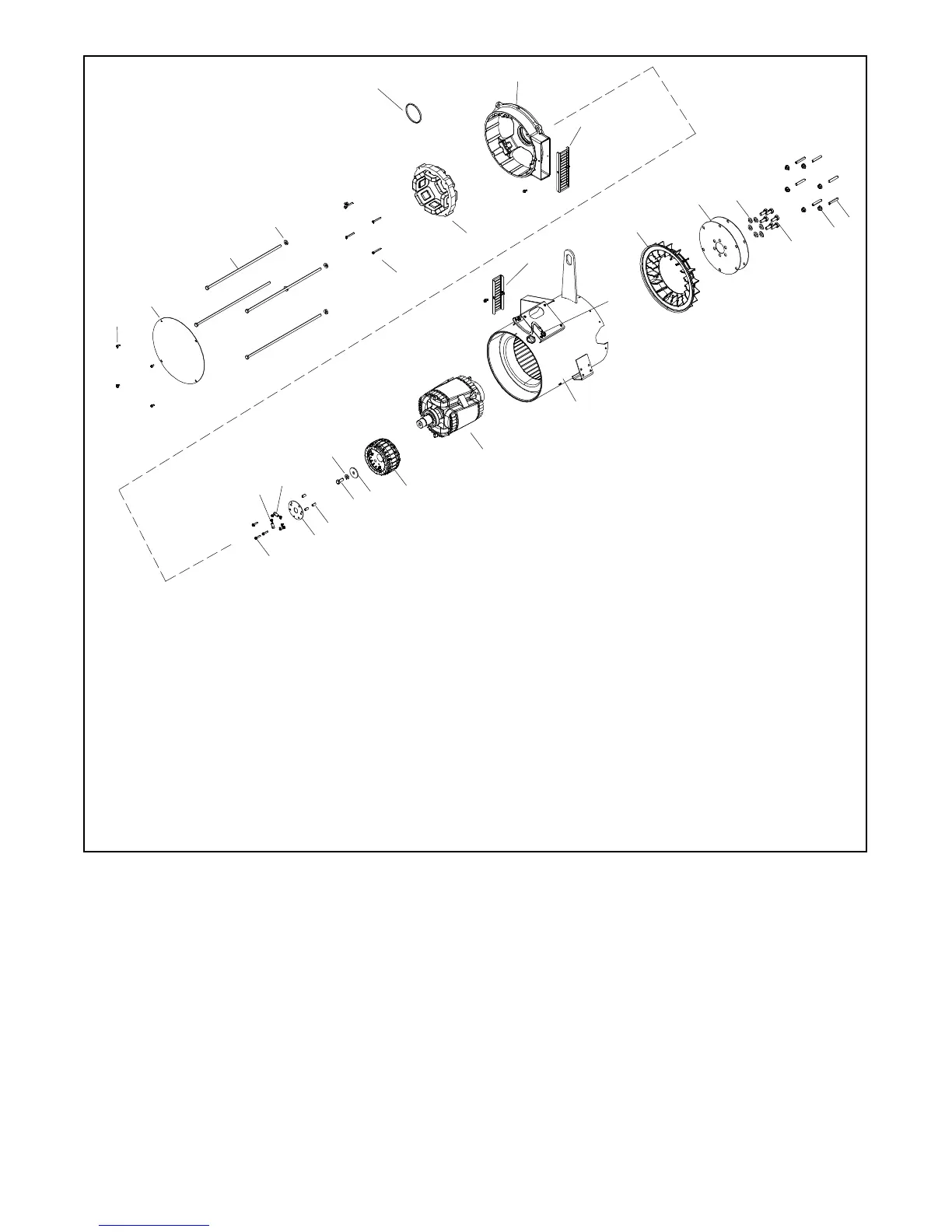
1. Screws and washers
2. End bracket panel
3. Overbolts. Torque to 23 Nm (17 ft. lbs.)
4. Washers
5. Screws
6. Exciter field assembly
7. O-ring. Assemble O-ring into groove in bearing insert.
8. End bracket
9. End bracket air inlet guard and screw
10. Screws
11. Screws and lock washers
12. Terminals
13. Rotating diode board
14. Spacers
15. Bolt. Torque to 38 Nm (28 ft. lbs.)
16. Lock washer
17. Washer
18. Exciter armature. Note: Apply a thin coat of anti-seize
compound to shaft surface before attaching exciter armature.
19. Rotor assembly
20. Stator assembly
21. Alternator air outlet guard and screw
22. Lead, screw, lock washer, and plain washer
23. Alternator fan
24. Drive disk
25. Washers
26. Screws. Torque to 45 Nm (34 ft. lbs.)
27. Nuts
28. Studs. Torque to 23 Nm (17 ft. lbs.)
1
2
3
4
5
6
9
8
7
28
27
26
25
24
23
21
22
20
19
18
16
17
15
14
12
13
11
10
Note: Use cable ties to restrain loose harness
leads from entangling in rotor.
Figure 9-6 9--11EKOZD/7--9EFKOZD Alternator Assembly (Disassembly/Reassembly)
Follow the general torque specification found in
Appendix C of this manual unless noted above or in
Section 1.6, Torque Specifications.
 Loading...


