4 — PROGRAMMABLE PARAMETERS
pg. 143
Return to TOC Curtis AC F2-A, F4-A, F6-A Motor Controllers – FOS 4.5 – April 2022
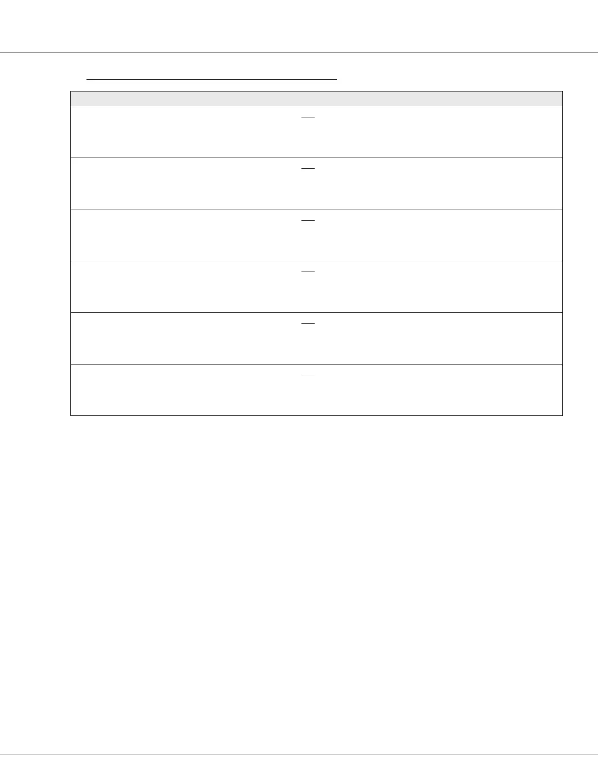
PARAMETER ALLOWABLE RANGE DEFAULT DESCRIPTION
Switch Hall Pattern 0
Switch_Hall_Pattern_0
0x50A6 0x00
Controller model basis
Auto generated by the
commissioning process
Used for copying
N/A
See the
RESULTS post
commissioning
Three Hall switches separate an electrical cycle of motor to six
sectors, and each sector has a sector pattern which consists
of the outputs of Hall switches. This parameter represents the
pattern of one sector.
Switch Hall Pattern 1
Switch_Hall_Pattern_1
0x50A7 0x00
Controller model basis
Auto generated by the
commissioning process
Used for copying
N/A
See the
RESULTS post
commissioning
Three Hall switches separate an electrical cycle of motor to six
sectors, and each sector has a sector pattern which consists
of the outputs of Hall switches. This parameter represents the
pattern of one sector.
Switch Hall Pattern 2
Switch_Hall_Pattern_2
0x50A8 0x00
Controller model basis
Auto generated by the
commissioning process
Used for copying
N/A
See the
RESULTS post
commissioning
Three Hall switches separate an electrical cycle of motor to six
sectors, and each sector has a sector pattern which consists
of the outputs of Hall switches. This parameter represents the
pattern of one sector.
Switch Hall Pattern 3
Switch_Hall_Pattern_3
0x50A9 0x00
Controller model basis
Auto generated by the
commissioning process
Used for copying
N/A
See the
RESULTS post
commissioning
Three Hall switches separate an electrical cycle of motor to six
sectors, and each sector has a sector pattern which consists
of the outputs of Hall switches. This parameter represents the
pattern of one sector.
Switch Hall Pattern 4
Switch_Hall_Pattern_4
0x50AA 0x00
Controller model basis
Auto generated by the
commissioning process
Used for copying
N/A
See the
RESULTS post
commissioning
Three Hall switches separate an electrical cycle of motor to six
sectors, and each sector has a sector pattern which consists
of the outputs of Hall switches. This parameter represents the
pattern of one sector.
Switch Hall Pattern 5
Switch_Hall_Pattern_5
0x50AB 0x00
Controller model basis
Auto generated by the
commissioning process
Used for copying
N/A
See the
RESULTS post
commissioning
Three Hall switches separate an electrical cycle of motor to six
sectors, and each sector has a sector pattern which consists
of the outputs of Hall switches. This parameter represents the
pattern of one sector.
MOTOR SETUP/PMAC/PERMANENT MAGNET MOTOR — COMMISSIONING RESULTS MENU, cont’d

 Loading...


