EasyManua.ls Logo

Kohler Curtis F Series User Manual

Kohler Curtis F Series
277 pages
To Next Page IconTo Next Page
To Previous Page IconTo Previous Page
Page #47 background imageLoading...
Page #47 background image
4 — PROGRAMMABLE PARAMETERS
pg. 39
Return to TOC Curtis AC F2-A, F4-A, F6-A Motor Controllers – FOS 4.5 – April 2022
SDO WRITE MESSAGE
To retain parameter values in non-volatile memory (NVM) via CANopen SDO write messages, rst
write the value of one (01h) to the Least Signicant [data] Byte (LSB) of the 32-bit parameter SDO_
NVM_Write_Enable (Object Index 0x2008, sub-index 0x00). is will cause parameter changes
to be written to non-volatile memory. Note that having the SDO_NVM_Write_Enable parameter
set to zero (0) only saves the parameter changes to ephemeral (RAM) memory. RAM values are
not stored over keyswitch cycles. Always return this parameter to the disabled state (= 0), when
nished writing parameter values/changes. e state can be checked in CIT using the List View
option in Programmer.
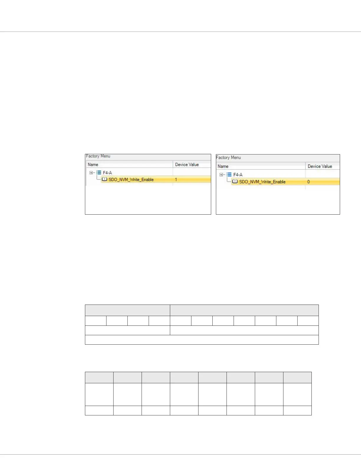
Use the CIT List-View image illustrated below (F4 example). In the rst image, the controller (Node
ID 0x26) is set to write parameter values to NVM (value = 1). In the second image (the default value
= 0), the controller will only write parameter values to RAM.
SDO_NVM_Write_Enable = 1 (enabled) SDO_NVM_Write_Enable = 0 (disabled)
In the example illustrated above, the SDO message to a controller with a Node ID = 26h (38d, 0010
0110b) is constructed by rst writing a value of “1” to the SDO_NVM_Write_Enable parameter
(enables), then a value of “0” (disables) as dened, below. Here, the data bytes are shown using the
1 – 8 nomenclature. It could as easily be labeled data bytes 0 – 7. e control byte uses the SDO-Rx
23h, as the parameter is 32-bits, so all data bytes are “written” even as the values in the data bytes are
zero (00h). e message format is Little Endian, therefore data byte #5 is the LSB.
COB-ID
Function Code Node ID of target Ancillary Controller
1 1 0 0 0 1 0 0 1 1 0
SDO-Rx Node 26h
COB-ID = 626h
SDO_NVM_Write_Enable (Object Index 0x2008, sub-index 0x00) = ‘enable’ (01 = 1 in byte 5,
the LSB)
Byte 1 Byte 2 Byte 3 Byte 4 Byte 5 Byte 6 Byte 7 Byte 8
Control
(write)
LSB
Object
Index
MSB
Object
Index
Sub
Index
Data Data Data Data
23h 08 20h 00 01 00 00 00

Table of Contents

Question and Answer IconNeed help?

Do you have a question about the Kohler Curtis F Series and is the answer not in the manual?

Kohler Curtis F Series Specifications

General IconGeneral
BrandKohler
ModelCurtis F Series
CategoryController
LanguageEnglish

Summary

1 — OVERVIEW

HOW TO USE THIS MANUAL

Guidance on navigating and utilizing the manual's content for effective controller application.

WHAT IS NEW IN FOS 4.5.0.0 ... HIGHLIGHTS

Summary of key enhancements and changes in the FOS 4.5.0.0 firmware version.

GETTING THE MOST OUT OF YOUR CURTIS CONTROLLER

Advice on optimizing controller application through understanding manual sections and tools.

2 — INSTALLATION AND WIRING

PHYSICALLY MOUNTING THE CONTROLLER

Instructions for proper physical installation and mounting of the controller for optimal performance and environmental protection.

PRECAUTIONS

Essential safety and design considerations for ensuring EMC compliance and preventing electrical issues.

HIGH CURRENT CONNECTIONS

Details on connecting high-current terminals (B+, B-, U, V, W) and recommended connection guidelines.

LOW CURRENT CONNECTIONS

Information on logic and low-power connections via AMPSEAL connectors, including pin assignments.

Rotor Position feedback

Guidance on wiring rotor position sensors, including signal wiring best practices and shielding.

CANbus

Best practices for CANbus wiring, including twisted-pair and shielded cable usage for reliable communication.

All other low power wiring

Recommendations for routing low-power wiring to avoid signal interference and protect against damage.

Protected voltages

Information on protected voltage ratings for low-power pins and crucial connection warnings to prevent damage.

3 — APPLICATION-SPECIFIC FEATURES

MOTOR SPEED CONSTRAINTS

Details on how electrical frequency, encoder pulses, and parameter settings limit maximum motor speed (RPM).

VOLTAGE LIMITS

Explanation of hardware and parameter-based voltage limits, including operating regions and thresholds.

BROWNOUT VOLTAGE

Information on the fixed brownout voltage level and controller actions when voltage falls below this threshold.

KSI AND B+ INPUT

Notes on KSI input connection to B+ terminal for controller power, precharge, and BDI usage.

BATTERY DISCHARGE INDICATOR

Explanation of the BDI algorithm for calculating battery state-of-charge (SOC) and its viewable parameters.

4 — PROGRAMMABLE PARAMETERS

PROGRAMMING MENUS

Overview of programmable parameters organized into nested menus for customization via CANbus connection.

PARAMETER CHANGE FAULTS [PCF]

Explanation of faults triggered when parameters are changed while the motor bridge is enabled.

MONITOR VARIABLES WITHIN PARAMETER MENUS

Information on specific monitor variables contained within parameter menus, which are read-only.

PROGRAMMING TOOLS

Details on PC-based Curtis Integrated Toolkit (CIT) and the Curtis 1313 handheld programmer.

5 — SYSTEM MONITOR MENU

MOTOR MENU

Displays real-time motor data including RPM, temperature, torque, power, and feedback signals.

VEHICLE MENU

Monitors vehicle speed, odometer, acceleration, and distance traveled, configurable in metric or English units.

FAULT HISTORY

Accesses and clears the controller's fault history file for diagnosing and verifying problem resolution.

6 — COMMISSIONING

INITIAL SETUP

Essential steps for setting up controller parameters and ensuring they are suited to the specific application.

TRACTION MOTOR SELECTION

Guidance on selecting and commissioning ACIM or PMAC motors, including compatibility and procedures.

AC Motor Characterization

Procedure for characterizing ACIM traction motors using a quadrature encoder or Sin/Cos sensor.

AC MOTOR TUNING GUIDE

Steps for tuning the AC traction motor performance by selecting control modes and adjusting parameters.

SETTING UP THE HYDRAULIC SYSTEM

Procedures for setting up hydraulic systems, including lift, lower, and load-hold valve controls.

7 — DIAGNOSTICS AND TROUBLESHOOTING

THE DIAGNOSTICS PROCESS

Methods for obtaining diagnostics information, including status indicators, programmer tool, and CAN emergency messages.

FAULT ACTIONS

Table detailing fault actions taken by the controller, including shutdown sequences and VCL references.

8 — MAINTENANCE

CLEANING

Procedure for routine cleaning of the controller exterior to protect against corrosion and electrical issues.

FAULT HISTORY

Accessing and clearing the controller's fault history file to diagnose and verify problem resolution.

APPENDIX A

CAN PDO MAP SETUP

Guidance on setting up PDO maps for F-Series controllers using the Curtis Integrated Toolkit™ for CAN communication.

APPENDIX B

ELECTROMAGNETIC COMPATIBILITY (EMC)

Information on emissions and immunity, and techniques to reduce EMC problems in products with Curtis controllers.

ELECTROSTATIC DISCHARGE (ESD) IMMUNITY

Necessary precautions to protect ESD-sensitive components from damage by providing sufficient distance or isolation.

DECOMMISSIONING AND RECYCLING THE CONTROLLER

Instructions for decommissioning and recycling the controller, following OEM and landfill directives.

APPENDIX C

EN 13849 COMPLIANCE

Overview of safety requirements and performance levels (PL) according to EN13849 for control systems.

APPENDIX D

CURTIS INTEGRATED TOOLKITTM

Description of CIT software for configuring and communicating with Curtis Instruments products via CAN network.

Choosing the CAN Interface Device Driver

Steps to select and install the appropriate CAN dongle driver for PC communication with the controller.

Creating a Project with a new F-Series controller

Step-by-step guide to opening the Project Explorer and creating a new project for F-Series controller configuration.

APPENDIX E

SPECIFICATIONS: CONTROLLER

Detailed specifications for AC F6-A, F4-A, and F2-A controllers, including electrical and mechanical data.

Related product manuals