4 — PROGRAMMABLE PARAMETERS
Curtis AC F2-A, F4-A, F6-A Motor Controllers – FOS 4.5 – April 2022 Return to TOC
pg. 90
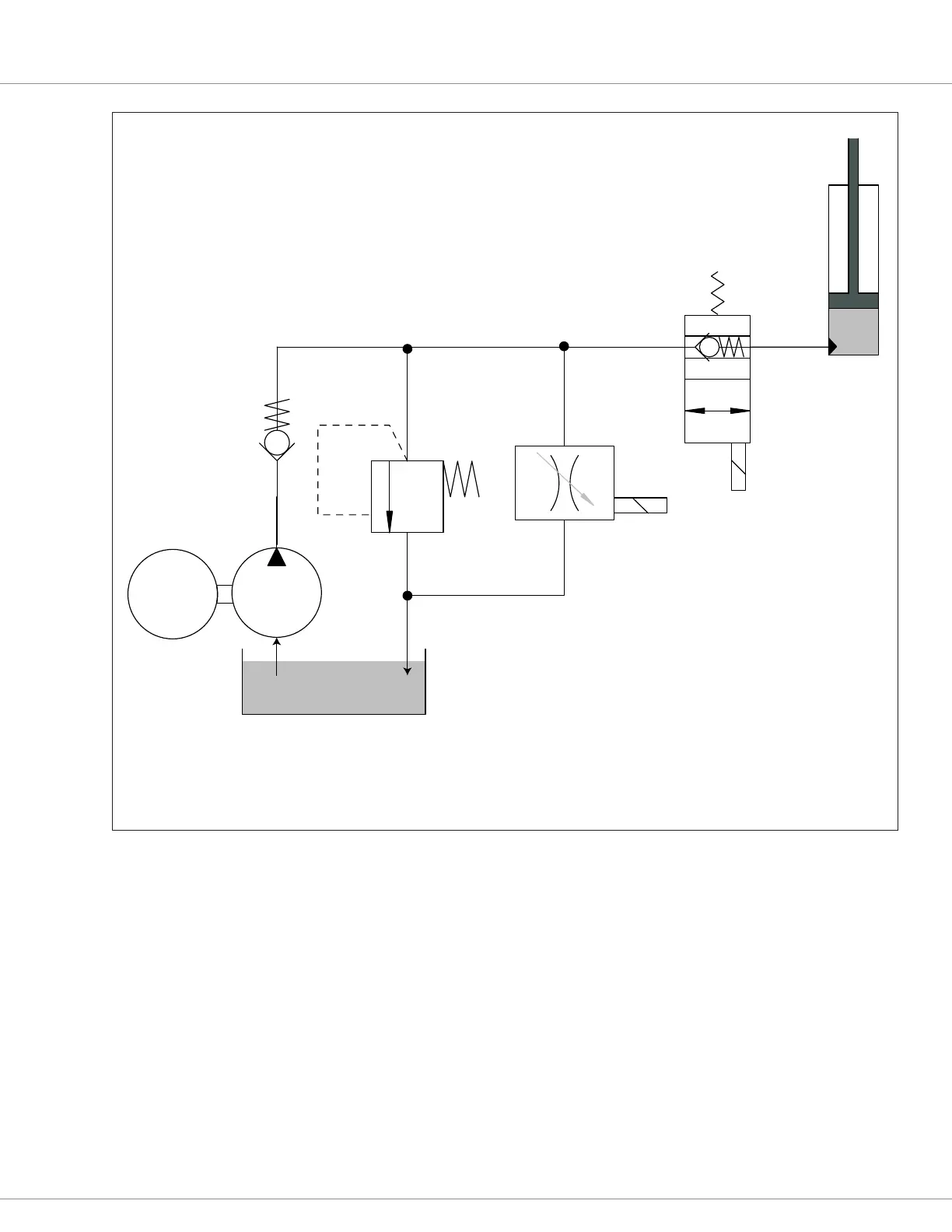
Figure 28
Hydraulic system diagram, with load-hold and proportional lower valves
DC
Pump
Motor
M
Pump
Reservoir
Proportional
valve
Load Hold
Valve
Check
Valve
Pressure
Relief
Lift Cylinder
This is a Proportional hydraulic lift/lower system. It allows for a
variable-rate lower through the use of a proportional valve (PV).
During Lift, the hydraulic pump forces fluid up the hoses,
through the open* load-hold valve (LHV), and into the
Lift cylinder. When the Lift is completed, the LHV closes,
trapping the fluid in the Lift cylinder (i.e., holds the load).
During Lower, the LHV is quickly opened and it is the PV that
regulates how quickly the fluid, under the force of gravity, returns
to the reservior. The proportional valve controls the lower rate
and the mid-cycle fork-level precision.
*The LHV opening delay (Load_Hold_Open_Delay)
is active during the start of any Lift operation.
- The speed of the DC pump motor regulates how quickly
the hydraulic fluid can push up the Lift cylinder.
- The aperature of the proportional valve regulates how quickly
and precisely the hydraulic fluid drains from the Lift cylinder,
whether to a specific point or to the fully-lowered position.

 Loading...


