4 — PROGRAMMABLE PARAMETERS
pg. 91
Return to TOC Curtis AC F2-A, F4-A, F6-A Motor Controllers – FOS 4.5 – April 2022
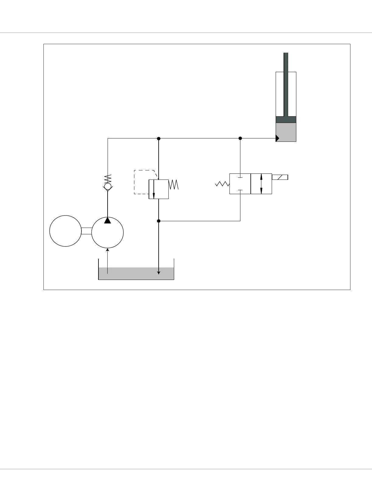
Figure 29
Hydraulic system diagram, with a xed (On/O) load-hold valve
DC
Pump
Motor
M
Reservoir
Pump
Load Hold
Valve
Check
Valve
Pressure
Relief
Lift Cylinder
This is a fixed (On/Off) hydraulic Lift/Lower System.
A Proportional (variable rate) lowering valve is not used.
The Load Hold Valve (LHV) is used as the lowering valve.
During Lift, the DC pump motor drives the hydraulic pump,
which forces hydraulic fluid up the hoses and into the Lift
cylinder. The LHV is closed (Off) during the Lift cycle.
When the Lift is completed, both the check valve and the
closed LHV trap the fluid in the Lift cylinder (holds the load).
During Lower, the LHV opens* and gravity returns the
fluid to the reservior. When lower is complete, the LHV
closes and this valve plus the check valve at the pump
keep the hydraulic fluid in the lift-circuit hoses.
*The LHV opening delay (Load_Hold_Open_Delay)
is not active during the Lower operation.
e hydraulics parameters adjust the system’s operating characteristics — knowing that for a non-
combi controller, the li settings apply to a minimal extent when setting the “trigger” points of the
type of li command input. A “switch to KSI voltage” is O/On. A VCL command of 0-100% is
similar, as is a voltage input into an analog input. Use the parameters to tailor the hydraulic system
to a specic application, or to a specic operator’s preferences, in conjunction with the parameters
in the Controls menu (Controller Setup » IO Assignments » Controls).
Figures 30 and 31 show the signal-chain process for the Lift and Lower functions. The inputs
applicable to a combi-controller are in light/greyed-out text. ese are not directly applicable to the
standard motor controllers. If a simple “switch” triggers the pump, notice its 0-100% step-response
in the throttle/switch mapping box. e CAN tiller system (Figure 14) will use a processed VCL
variable to drive the pump motor, skipping the throttle-mapping block and utilizing the VCL_Li_
rottle_Enable (On/O) and VCL_Li_rottle (%) functions. Use these Li and Lower process
gures as a guide to the appropriate hydraulics parameters, VCL functions, and the parameters in
the Controls menu (Controller Setup » IO Assignments » Controls). Hint: Review how the traction
throttle and brake throttle signal chains operate.
Quick Links:
Fig. 14 p.18

 Loading...


