TP-6984 5/17a16 Section 1 Installation
1.7.3 Connecting the Fuel Supply
The dimension drawing in Section 3 shows the location
of the fuel inlet connection. Have the fuel supplier install
rigid gas piping and a manual fuel shut-off valve. The
fuel supply line should line up with the generator set fuel
inlet and end about 12 inches away to allow connection
with a section of flexible fuel line. Use flexible sections to
prevent fuel line breakage caused by vibration.
Note: Do not bend the flexible fuel line to make up for
misalignment of the fuel supply line and the
generator set fuel inlet.
Apply pipe sealant that is approved for fuel connections.
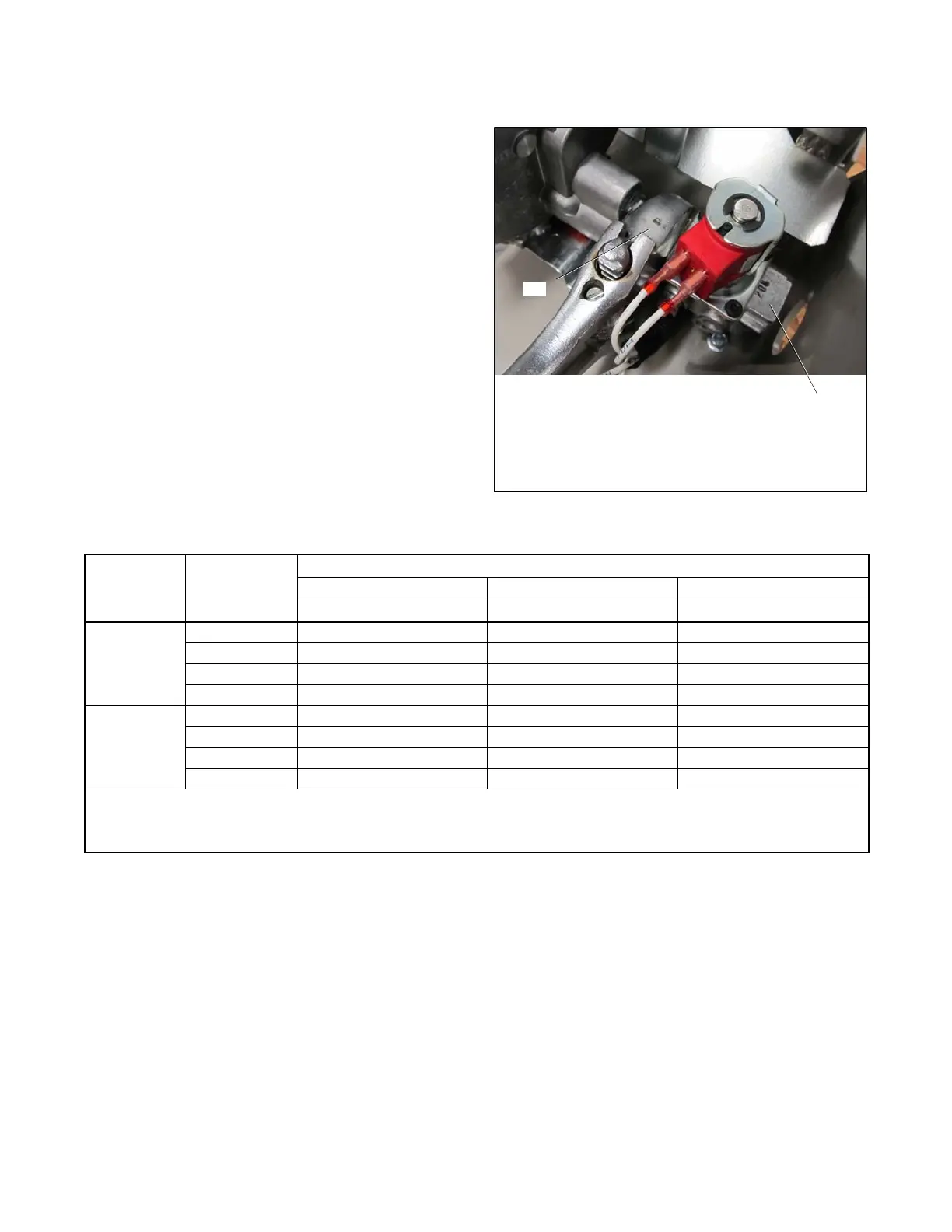
Hold the fuel solenoid valve with a wrench when
tightening the fuel connections.
Note: Do not hold the fuel solenoid valve coil when
tightening the fuel connections. See Figure 1-8
for the recommended wrench locations.
Open the manual fuel valves and test all fuel
connections using soapy water. If a leak is found, close
the fuel valves, clean the fittings, and apply fresh
sealant. Check for fuel leaks again with the generator
set running.
Protect all fuel lines from machinery or equipment
contact, adverse weather conditions, and environmental
damage.
2
1. Hold valve with wrench on flats of valve body
2. Alternate wrench location
Note: Do NOT hold the valve coil when tightening connections.
1
Figure 1-8 Holding Fuel Valve to Tighten Fuel
Connections
Fuel Type % Load
Fuel Consumption, m
3
/hr. (cfh)
8RESV/RESVL 10RESV/RESVL 12RESV/RESVL
60 Hz 60 Hz 60 Hz
Natural Gas
100% 3.9 (136) 5.1 (179) 6.1 (216)
75% 2.7 (95) 4.1 (145) 4.5 (160)
50% 2.0 (69) 3.4 (120) 3.6 (128)
25% 1.5 (53) 2.7 (97) 2.8 (99)
LPG
100% 1.7 (59) 2.5 (89) 2.9 (103)
75% 1.3 (45) 2.0 (69) 2.2 (76)
50% 1.0 (36) 1.5 (52) 1.6 (57)
25% .75 (26) 1.1 (39) 1.2 (42)
LPG conversion factors:
8.58 ft.
3
=1lb.
0.535 m
3
=1kg
36.39 ft.
3
= 1 gal.
Nominal fuel rating:
Natural gas: 37 MJ/m
3
(1000 Btu/ft.
3
)
LPG: 93 MJ/m
3
(2500 Btu/ft.
3
)
Figure 1-9 Fuel Consumption
 Loading...

