TP-6984 5/17a 21Section 1 Installation
Procedure
1. Drill holes for the conduit fittings. See Figure 1-16
for the recommended electrical inlet locations.
Feed the cables through the openings.
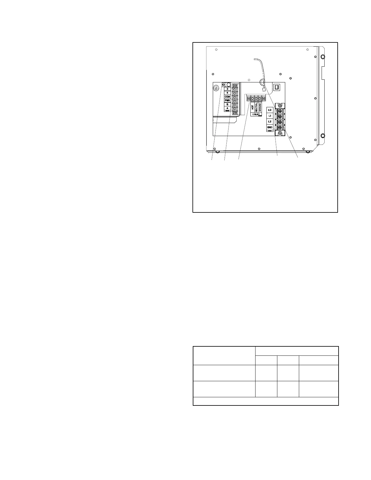
2. Connect the leads from the transfer switch
emergency source lugs to the L1 and L2
connections on the generator set terminal block.
3. Connect the neutral (L0) and ground (GRD) leads
from the ATS and the main panel to the
corresponding connection points on the terminal
block. See Section 1.9.1, Grounding.
4. Connect utility power leads to the terminal block
connections labelled UTILITY. Connect to a circuit
that is supplied by the utility source and backed up
by the generator. See Section 1.9.4 for more
information about the utility power requirement.
5. For connection of optional transfer switches, the
programmable interface module (PIM), and/or a
load shed kit, see Section 1.10.
6. To connect the OnCuer Plus Generator
Management System to your generator, run
network cable from the generator set to the
customer’s router or modem.
a. Route the network cable with other low-voltage
signal wiring (for example, the RBUS
communication leads or engine start leads to
the transfer switch), in separate conduit from
the AC load leads. If the network cable is longer
than 100 meters (328 ft.), use a repeater or
switch.
b. Test the internet connection for the generator
by connecting a laptop to the network cable.
(1) Turn OFF any wireless connections to the
laptop.
(2) Connect the network cable to the laptop.
Connect the other end of the network cable
to the customer’s router or modem.
(3) Verify the Internet connection by opening
your web browser and going to
www.kohlerpower.com or any known
website.
(4) Disconnect the network cable from the
laptop.
c. Use an RJ45 inline coupler to connect the
Ethernet cable to the cable in the customer
connection box. See Figure 1-18. The inline
coupler is included with the OnCue Plus kit.
7. When connections to the terminal block are
complete, r eplace the cover plate.
1. Ground connection for communication cable shield.
2. Low voltage communication and engine start
connections
3. AC power connections
4. Ethernet cable for OnCue Plus connection
5. AC load connections
GM88354
5
1
2
3
4
Figure 1-18 Electrical Connections
1.9.4 AC Power Supply
The installer must connect AC power for the battery
charger (which is integral to the RDC2 controller) and
the optional accessories shown in Figure 1-19. The
power source must comply with state and local codes.
The power to the battery charger and accessories must
be backed up by the generator so that power is available
at all times.
Be sure to disconnect power at the distribution panel
before making the connections. Connect power leads to
the utility power connection points on the terminal block.
See Section 1.9.3 and the wiring diagrams in Section 3
for connection details.
Equipment
Power Requirement, Max.
Watts Amps Volts
Battery charger (stand-
ard)
50 0.4
100--250 VAC
50/60 Hz
Carburetor heater *
37 0.3
120 VAC
50/60 Hz
* Optional accessory
Figure 1-19 Power Requirements
 Loading...

