TP-6984 5/17a 33Section 2 Accessories
Section 2 Accessories
2.1 Introduction
This section describes some of the accessories that are
available for the generator sets. Have accessories
installed by an authorized distributor/ dealer or a
licensed electrician. This document does not contain
installation instructions for accessories. Follow the
installation instructions provided with each kit.
Use separate conduit for AC and DC leads to reduce the
possibility of electrical interference. Verify that the leads
and conduit do not interfere with the operation of the
generator set or obstruct the service areas. Verify that
the electrical installation complies with the National
Electrical Code (NEC) and all applicable local codes.
See the wiring diagrams in Section 3 for more
information regarding generator set electrical
connections.
2.2 Connect Optional
Programmable Interface
Module (PIM)
The optional programmable interface module (PIM)
provides two programmable inputs and six dry contact
outputs, four of which are programmable. See TT-1584
for PIM installation and connection instructions. Also
see Section 1.10 of this manual for connection to the
generator set.
The default settings for the inputs and outputs are
shown in Figure 2-2. To change the input and output
settings, use a personal computer running Kohler
SiteTechr software. See TP-6701, SiteTech Software
Operation Manual, for instructions.
Kohler OnCuer Plus can be used to actively control PIM
outputs. See the OnCue Plus Operation Manual for
instructions.
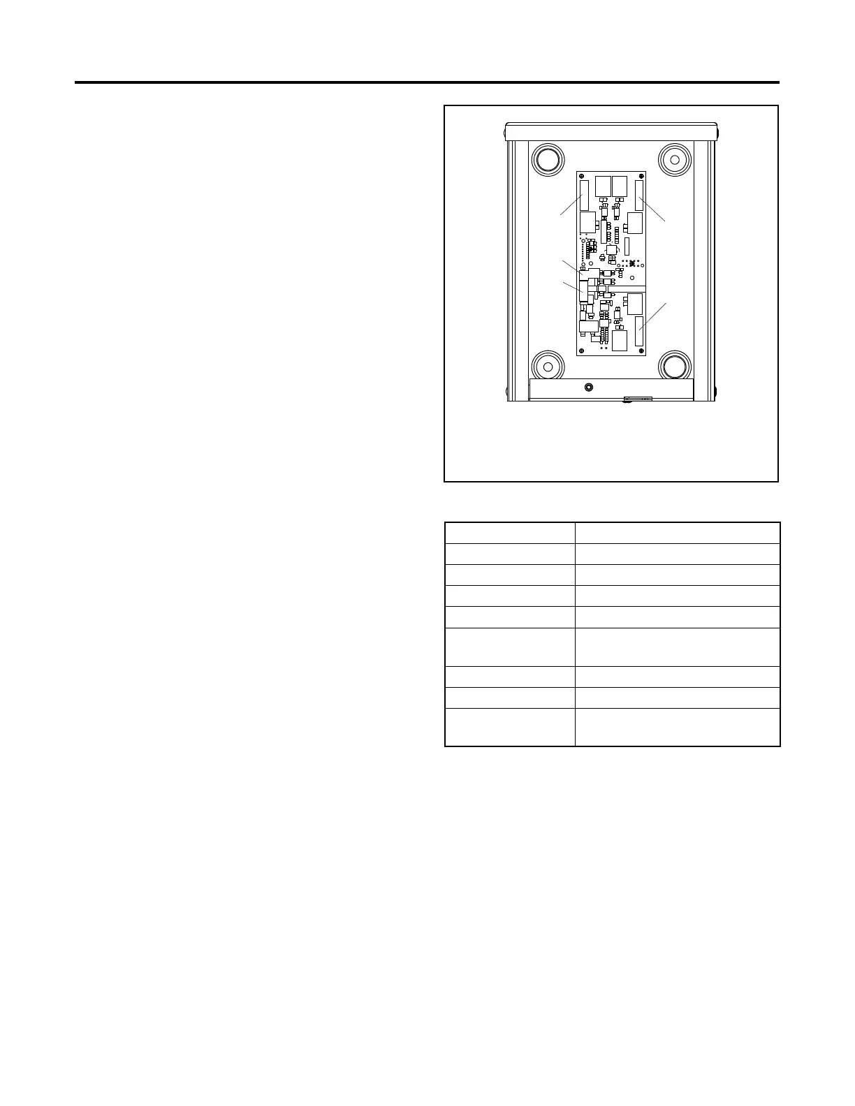
1. Output connections (3 terminal blocks, 6 outputs)
2. Input connections (2 inputs)
3. RBUS communication connection to generator set terminal
block TB2
2
ADV-8199
1
3
1
1
Figure 2-1 Optional PIM
PIM Connection Factory Default Setting
Input 1 None
Input 2 None
Output 1 (Relay 1) Run
Output 2 (Relay 2) Common Fault
Output 3 (Relay 3) Low Battery Voltage (Program-
mable)
Output 4 (Relay 4) Not in Auto (Programmable)
Output 5 (Relay 5) Cooldown (Programmable)
Output 6 (Relay 6) Normal Source Failure (Program-
mable)
Figure 2-2 PIM Inputs and Outputs
 Loading...

