TP-6984 5/17a34 Section 2 Accessories
2.3 Load Management
On models 8RESV, 10RESV, and 12RESV, two optional
load management devices are available for use when
combined with a model RXT and RDT transfer switch:
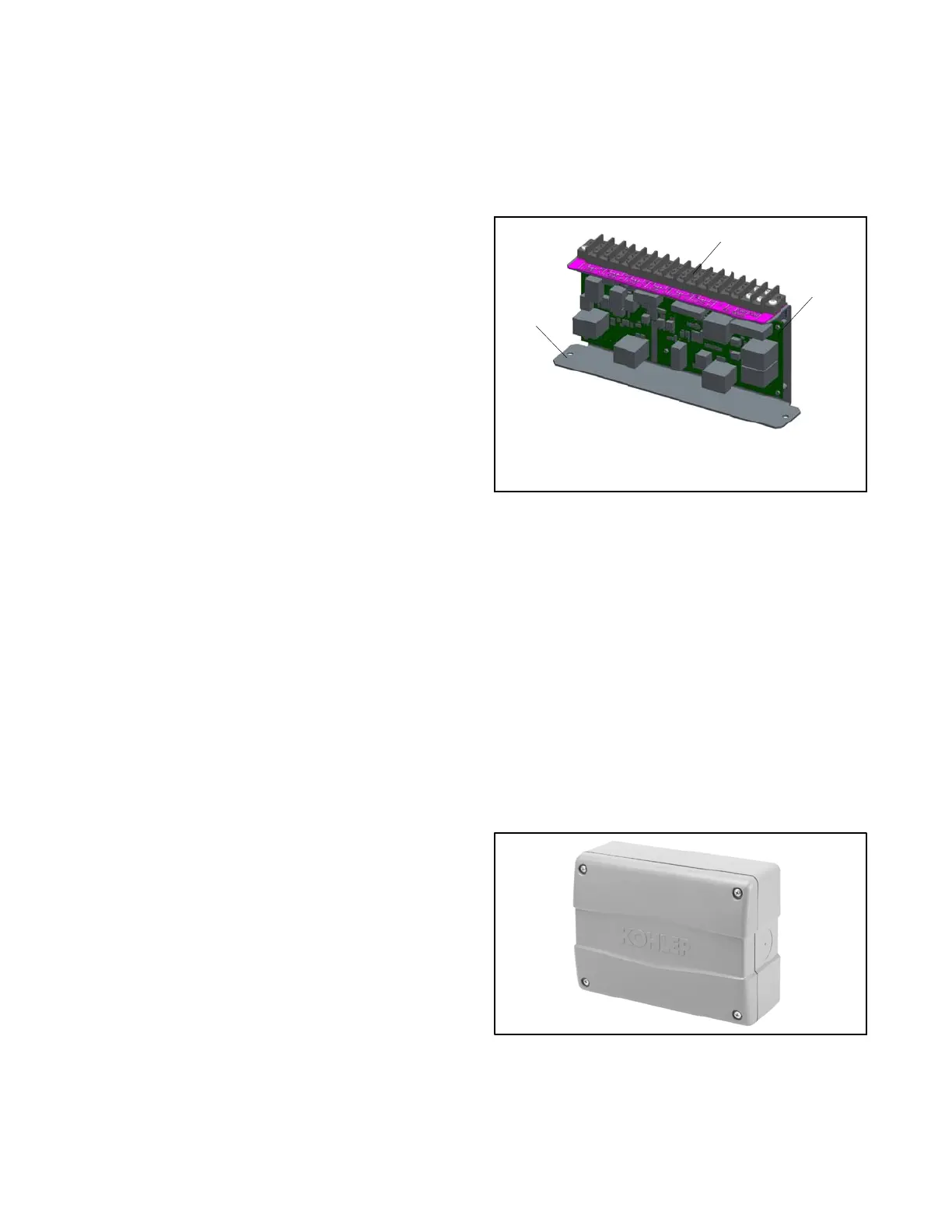
D The optional Load Shed Kit mounts inside a model
RDT or RXT transfer switch. Figure 2-3 shows the
load shed assembly.
D The combined interface/load management board is
available for the Model RXT transfer switch.
Note: Load shed kits are not available with the transfer
switch supplied with models 8RESVL, 10RESVL,
12RESVL.
The devices provide an automatic load management
system to comply with Section 702.5 of NEC 2008.
Note: The load management devices are only
compatible with single-phase generator sets.
With a load management system, less critical
appliances can be powered by the generator set when
the more important appliances are not running, allowing
the use of a smaller generator set than would be needed
to run all of the building’s electrical equipment at the
same time.
The load management device automatically manages
up to six residential loads.
D Two relays are included to control two independent
heating, ventilation, and air conditioning (HVAC)
loads.
D Up to four power relays (or load management
modules) can be connected through normally open
relay contacts on the circuit board. Load
management modules are available separately.
Load management modules include one power relay
mounted inside a NEMA type 3R enclosure. Connect up
to four (4) load management modules to the load
management devices listed above.
The load management device receives commands from
the RDC2 or DC2 generator controller and energizes or
de-energizes the appropriate load relays to add or shed
non-critical loads according to their priority.
Note: Connect only non-essential loads to the load
shed kit.
An adequate electrical supply is required for operation
of the customer-supplied power relays connected to the
load shed kit. Check the electrical requirements of the
customer-provided equipment prior to installation to
determine the wire size and circuit protection required.
The installer is responsible for ensuring that the power
system installation complies with all applicable state
and local codes.
For detailed installation and connection instructions,
see TT-1609, provided with the load shed kit, or
TP-6807, Operation/Installation Manual for the Model
RXT transfer switch with combined interface/load
management board.
1. Terminal block TB10
2. Load control circuit board
3. Mounting bracket
Note: Kit includes current transformer (CT), not shown.
2
GM88281
1
3
Figure 2-3 Load Shed Assembly GM88281-1
(mounts inside the transfer switch
enclosure)
2.3.1 Power Relay Module
The power relay module kit contains one 50 amp relay
with connecting lugs in a NEMA type 3R enclosure.
Connect up to four (4) power relay modules to the load
management devices listed above.
The power relay modules can be mounted indoors or
outdoors. Two (2) 120 VAC loads (shed simultaneously)
or a single 240 VAC load can be wired to each relay.
For detailed installation and connection instructions,
see TT-1646, provided with the power relay module kit.
Figure 2-4 Power Relay Module
 Loading...

