TP-6984 5/17a 23Section 1 Installation
Engine start c onnection for other transfer
switches or a remote start/stop switch
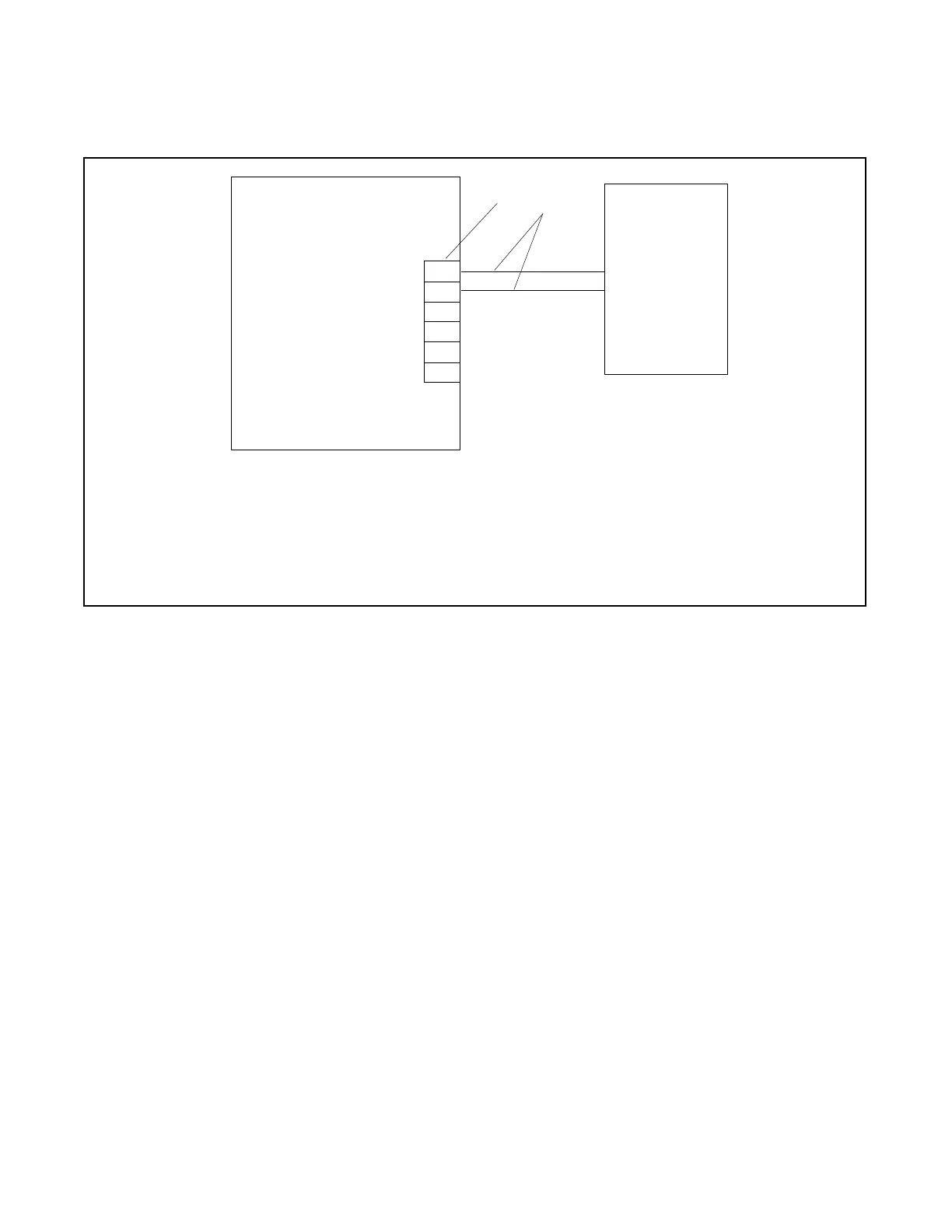
Connect the engine start leads from the transfer switch
or remote start switch to terminals 3 and 4 on the
terminal block. See Figure 1-21. Route the engine start
leads through separate conduit from the AC power and
load leads.
tp6803
1. Generator Set Terminal Block. See the dimension drawings in Section 3 for location. Check the decal on the generator set for terminal
block connections.
2. Engine start leads 3 and 4. See the ATS manual for cable size specifications.
Generator Set ATS
(with e ngine
start contacts)
1
2
A
B
COM
PWR
3
4
TB3
Figure 1-21 Engine Start Connections with Transfer Switch Models other than Model RXT
 Loading...

