Governor System
10362 690 05 Rev. H KohlerEngines.com
FIELD INSTALLED UPDATED DESIGN Electronic Governor Troubleshooting Flow Chart Continued
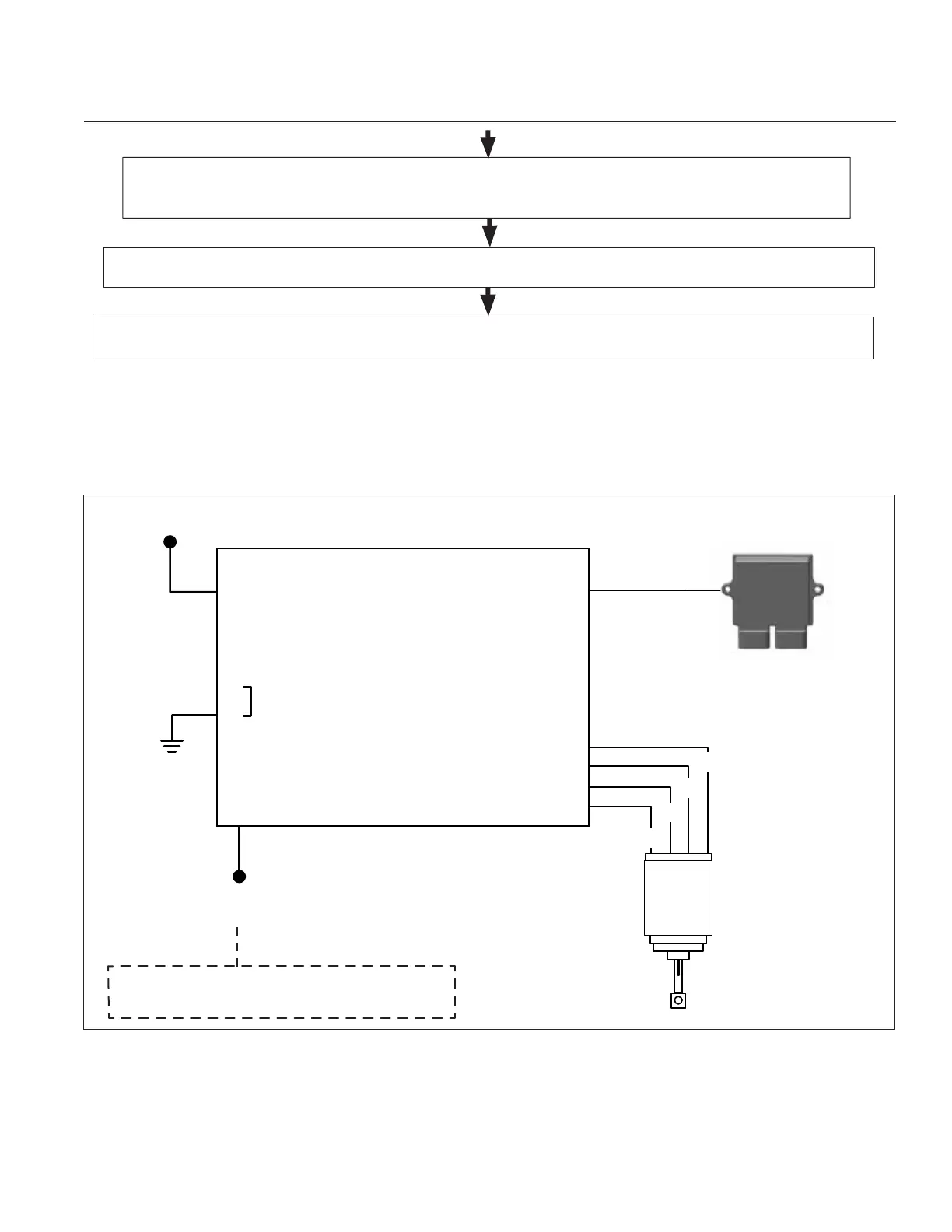
Basic Electrical Diagram of Electronic Governor System
If test fails, DLA is no good and should be replaced. If DLA test is good, another component, connection, or
input is most likely at fault.
DLA function can be tested and confi rmed using a stepper motor controller tool. Refer to Tools and Aids.
Testing instructions are included with tool.
Turn key switch to ON position. Test supply voltage to GCU using volt meter. Refer to page 97. (Battery
voltage +/- 1 volt)
B+
10
8
12
13
14
1
2
6
7
1B
1A
2A
2B
Application Supplied
Speed Control Input
Operation Input Voltage:
0-1 Volts at Idle/9+ Volts at High Speed
Device
Ground
Power
Speed Signal
ECU Speed Output
(speed signal)
DLA Driver
Controls
DLA
ECU
*
*
Green LED Light
Yellow LED Light
 Loading...