3162 690 05 Rev. H KohlerEngines.com
EFI SYSTEM-ELECTRONIC THROTTLE BODY (ETB)
ELECTRICAL COMPONENTS
Electronic Control Unit (ECU)
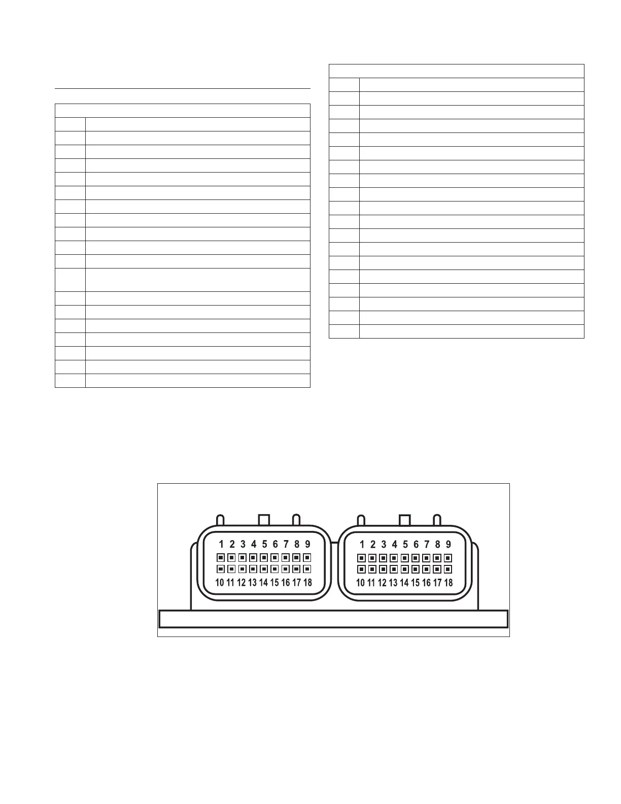
Pinout of ECU
Black Connector Side
Pin # Description
1 Ignition Coil #1 Ground
2 Battery Ground
3 Not Used
4 Crankshaft Position Sensor Input High
5 Fuel Injector Output #1 Ground
6 Fuel Injector Output #2 Ground
7 Oxygen Sensor Heater
8 Intake Air Temperature (TMAP) Sensor Input
9 Fuel Pump Ground
10 Ground for TPS, TMAP, O2, and Temp sensors
11
Manifold Absolute Pressure (TMAP) sensor
input
12 Throttle Position Sensor (TPS) input
13 Crankshaft Position Sensor Low
14 Engine Temperature Sensor input
15 Ignition Switch (Switched +12V)
16 Power for TPS and TMAP sensor (+5V)
17 Oxygen Sensor (O2) input
18 Battery Power (Permanent +12V)
Grey Connector Side
Pin # Description
1 Not Used
2 Not Used
3 Malfunction Indicator Light (MIL) Ground
4 Not Used
5 Not Used
6 Not Used
7 CAN Low
8 CAN High
9 Battery Ground
10 Ignition Coil #2 Ground
11 ETB Motor High
12 ETB Motor Low
13 Desired Engine Speed Input (0-5V)
14 Safety Switch Ground
15 Not Used
16 ECU Reset
17 Fuel Pump Control (+12V)
18 Not Used
BLACK CONNECTOR SIDE GREY CONNECTOR SIDE
ECU
Pinout of ECU