2762 690 05 Rev. H KohlerEngines.com
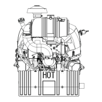
EFI SYSTEM-ELECTRONIC THROTTLE BODY (ETB)
WARNING
Explosive Fuel can cause fi res and severe
burns.
Do not fi ll fuel tank while engine is hot or
running.
Gasoline is extremely fl ammable and its vapors can
explode if ignited. Store gasoline only in approved
containers, in well ventilated, unoccupied buildings,
away from sparks or fl ames. Spilled fuel could ignite if it
comes in contact with hot parts or sparks from ignition.
Never use gasoline as a cleaning agent.
Typical electronic fuel injection (EFI) system and related
components include:
● Fuel pump module and lift pump.
● Fuel fi lter.
● High pressure fuel line.
● Fuel line(s).
● Fuel injectors.
● Electronic throttle body (ETB)/intake manifold.
● Electronic control unit (ECU).
● Ignition coils.
● Engine temperature sensor.
● Throttle position sensor (TPS) is contactless and not
serviceable.
● Crankshaft position sensor.
● Oxygen sensor.
● Temperature/manifold absolute pressure (TMAP)
sensor.
● Malfunction indicator light (MIL)-optional.
● 30 Amp fuse (charging system).
● Refer to equipment manual for fuse detail in OEM
supplied wiring harness (high output charging system).
● 10 Amp fuse (ignition switch).
● 10 Amp fuse (battery power).
● Wire harness assembly & affi liated wiring.
FUEL RECOMMENDATIONS
Refer to Maintenance.
FUEL LINE
Low permeation fuel line must be installed on all Kohler
Co. engines to maintain EPA and CARB regulatory
compliance.
OPERATION
NOTE: When performing voltage or continuity tests,
avoid putting excessive pressure on or against
connector pins. Flat pin probes are
recommended for testing to avoid spreading or
bending terminals.
EFI system is designed to provide peak engine
performance with optimum fuel effi ciency and lowest
possible emissions. Ignition and injection functions
are electronically controlled, monitored and continually
corrected during operation to maintain ideal air/fuel ratio.
Central component of system is Electronic Control Unit
(ECU) which manages system operation, determining
best combination of fuel mixture, ignition timing, throttle
opening and/or engine RPM for current operating
conditions.
ETB engines feature an ECU that uses CAN BUS/
J1939 communication protocols and may be linked to
other electronic control modules installed on application.
Please refer to equipment manufacturer's manual to
determine if equipped and operational detail. Native fault
codes are in line with J1939 protocol. We continue to
reference P Codes for consistency.
A lift fuel pump is used to move fuel from tank through
an in-line fuel fi lter and fuel line. Fuel is then pumped
to fuel pump module. Fuel pump module regulates
fuel pressure to a system operating pressure of 39 psi.
Fuel is delivered from fuel pump module through high
pressure fuel line into injectors, which inject fuel into
intake ports. ECU controls amount of fuel by varying
length of time that injectors are on. This can range
from 2 to over 12 milliseconds depending on fuel
requirements. Controlled injection of fuel occurs every
other crankshaft revolution, or once for each 4-stroke
cycle. When intake valve opens, air/fuel mixture is drawn
into combustion chamber, compressed, ignited, and
burned.
ECU controls amount of fuel being injected and ignition
timing by monitoring primary sensor signals for engine
temperature, operator requested engine speed (RPM),
and throttle position (load). These primary signals are
compared to preprogrammed maps in ECU computer
chip, and ECU adjusts fuel delivery to match mapped
values. After engine reaches operating temperature,
an exhaust gas oxygen sensor provides feedback to
ECU based upon amount of unused oxygen in exhaust,
indicating whether fuel mixture being delivered is rich or
lean. Based upon this feedback, ECU further adjusts fuel
input to re-establish ideal air/fuel ratio. This operating
mode is referred to as closed loop operation. EFI
system operates closed loop when all three of following
conditions are met:
● Engine temperature is greater than 50-60°C
(122-140°F).
● Oxygen sensor has warmed suffi ciently to provide a
signal (minimum 400°C, 752°F).
● Engine operation is at a steady state (not starting,
warming up, accelerating, etc.).
During closed loop operation ECU has ability to readjust
and learn adaptive controls, providing compensation
for changes in overall engine condition and operating
environment, so it will be able to maintain ideal air/
fuel ratio. This system requires a minimum engine
temperature greater than 50-60°C (122-140°F) to
properly adapt. These adaptive values are maintained as
long as ECU is not reset.
During certain operating periods such as cold starts,
warm up, acceleration, high load, etc., a richer air/fuel
ratio is required and system operates in an open loop
mode. In open loop operation oxygen sensor output is
used to ensure engine is running rich, and controlling
adjustments are based on primary sensor signals and
programmed maps only. This system operates open
loop whenever three conditions for closed loop operation
(above) are not being met.