Disassembly/Inspection and Service
126 62 690 05 Rev. HKohlerEngines.com
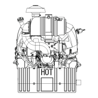
M Electrical Connector N Evap Line O
High Pressure Fuel
Line Connector
P
Oil Cooler (Engine
Mounted)
Q Oil Filter R
Blower Housing with
Fixed Guard
S Cylinder Shroud T
Fan/Flywheel
Assembly
Clean all parts thoroughly as engine is disassembled.
Only clean parts can be accurately inspected
and gauged for wear or damage. There are many
commercially available cleaners that will quickly remove
grease, oil and grime from engine parts. When such a
cleaner is used, follow manufacturer’s instructions and
safety precautions carefully.
Make sure all traces of cleaner are removed before
engine is reassembled and placed into operation. Even
small amounts of these cleaners can quickly break down
lubricating properties of engine oil.
NOTE: This disassembly sequence removes some
components in subassemblies to enable
technician to perform internal engine servicing.
Do not disconnect every EFI, electronic
governor, or electronic throttle body (ETB)
component.
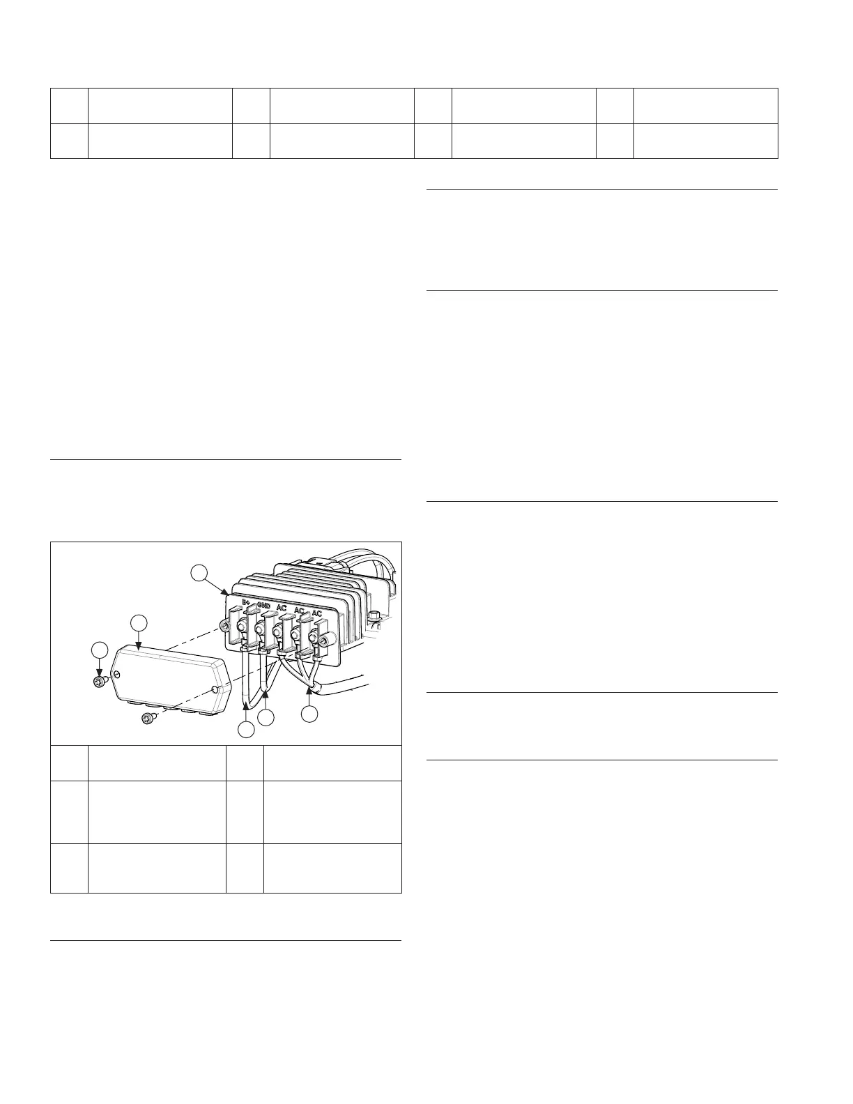
Remove High Output Charging System Terminal
Block Cover and Disconnect Stator Wires
NOTE: When high output charging system rectifi er-
regulator is supplied by Kohler, but installed by
OEM in application, you must remove terminal
block cover and disconnect stator wires before
removing engine from application.
D
C
A
B
E
F
A Torx Screw B
Terminal Block
Cover
C Rectifi er-Regulator D
OEM Supplied B+
Wiring Harness
with Charging
Fuse
E
OEM Supplied
Ground Wire
Harness
F Stator Wires
Disconnect Spark Plug Leads
NOTE: Pull on boot only, to prevent damage to spark
plug lead.
1. Disconnect leads from spark plugs.
2. Shut off fuel supply.
Drain Oil from Crankcase and Remove Oil Filter
1. Clean oil fi lter and housing area. Remove and
discard oil fi lter.
2. Remove dipstick and 1 oil drain plug.
3. Allow ample time for oil to drain from crankcase.
Remove Muffl er (if equipped)
NOTE: Unless oxygen sensor is damaged or
malfunctioning, disassembly from muffl er is
unnecessary.
1. Disconnect oxygen sensor connector from wire
harness.
2. Carefully remove sensor plug from bracket (ETB
ECV EFI only).
3. Remove exhaust system and attaching hardware
from engine. On engines equipped with port liners,
remove then now.
4. Remove oxygen sensor.
Remove Cylinder Shrouds and Blower Housing
1. Remove top mounting screw and loosen shoulder
screws on each side. Lift off cylinder shrouds.
2. Remove mounting screws and separate blower
housing from backing shroud assembly. One screw
also secures oil fi ll/dipstick tube. Fixed guard (if
equipped) may be removed with blower housing.
If engine has pulse/lift pump mounted to blower
housing, remove two mounting screws.
3. Remove lower mounting screw and pull oil fi ll tube
out of crankcase.
Remove Electric Starter Motor
1. Disconnect leads from starter.
2. Remove screws and starter.
Remove #1 Barrel and Valley Baffl es
NOTE: Unless ignition coil is being replaced,
disassembly from barrel baffl e is unnecessary.
1. Remove mounting screws from #1 barrel baffl e.
Disconnect wiring harness from coil (#1 starter side).
Let barrel baffl e hang (with coil installed).
2. If equipped, carefully remove clip securing wires to
#1 valley baffl e. Remove screws, then valley baffl e.
If necessary, remove screws securing rectifi er-
regulator (standard ignition) for access to top barrel
baffl e screw.
 Loading...