63
EFI SYSTEM
62 690 05 Rev. H KohlerEngines.com
AB AB ABC DABC 1 2 312ABC AB12
12
19
1018
19
1018
312
6
4
5
12
3
4
312
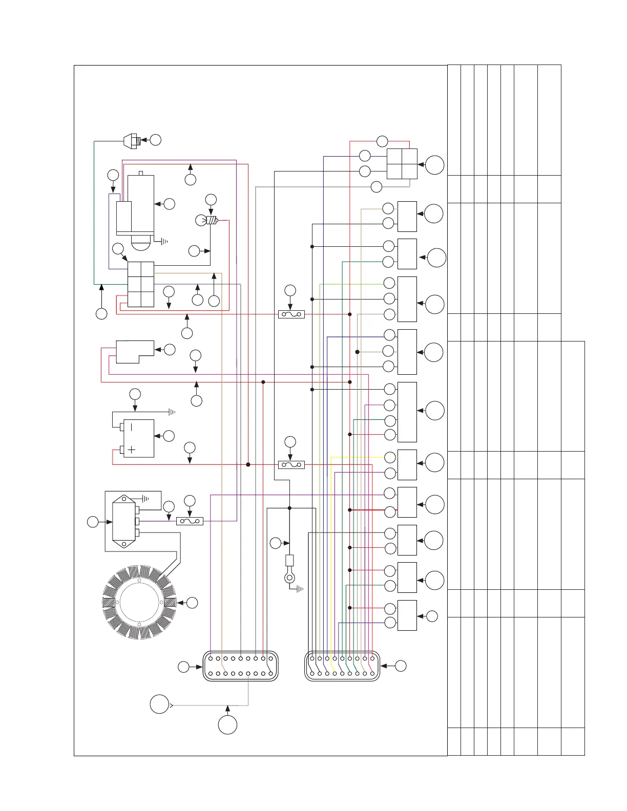
EFI Wiring Diagram 6-Terminal Connector (engines with separate MAP sensor and intake air temperature sensor)
A Red B Red/Black C Red/White D Yellow E Light Green
F Dark Green G Dark Blue H Purple I Pink J Tan
K White L Grey M Black N Stator O Rectifi er-Regulator
P 30A Fuse Q Battery R Fuel Pump S 6-Terminal Connector T Starter Motor
U Oil Pressure Switch V MIL (Optional) W 10A Fuse X Black Connector Y Grey Connector
Z Fuel Injector #1 AA Fuel Injector #2 AB Ignition Coil #1 AC Ignition Coil #2 AD
Crankshaft Position
Sensor
AE Oxygen Sensor AF
Throttle Position
Sensor
AG
Manifold Absolute
Pressure Sensor
AH
Oil Temperature
Sensor
AI
Intake Air
Temperature Sensor
AJ Diagnostic Connector AK Grey/Blue AL
Electronic Governor
only
C
J
G
B
F
B
B
M B
H
H
D B
F
H
M
M
L
G L
M
E
F
M
M
J
K
M G
B
K
W
AP
H
I
V
W
O
Y
M
M
N
X
Q
R
T
U
Z
AA
AB
AC
AD
AE
AF
AG
AH
AI
AJ
G
F
M
B
S
AL
AK
A
A
 Loading...