74 75
73
8
- 43 -
DISASSEMBLY/REASSEMBLY
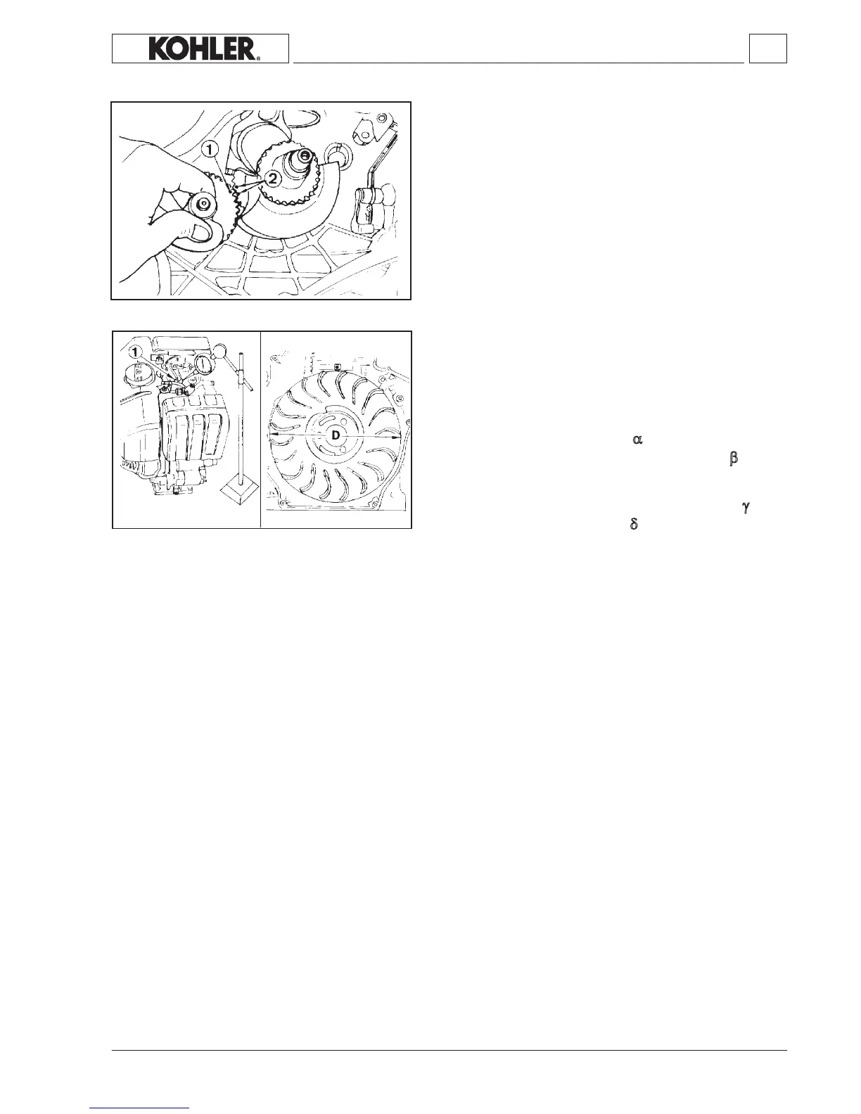
Dinamic balancer timing
Positioncrankshaftasshowninthegure.
Introduce the dynamic balancer so that timing mark 1 engages
betweenteeth2 ofthecrankshaftgear.
Valve timing check
Removethetankandconveyortoaccesstheywheel.
Carry out the inspections on the drive shaft. The values given are
measuredonthecircumferenceoftheywheel.
Adjustthevalveplayasindicatedonthenextpage.
Reset the comparator on the cap of intake valve 1. Turn the drive
shaftinthe spinning directionand nd α (point at whichtheintake
valvestartstoopeninrelationtotopdeadcenterA)and β (pointat
whichtheintakevalveshutsafterbottomdeadcenter B)seeg.77-
78.
Proceed in a similar way with the exhaust valve, checking γ (point
atwhichtheexhaustvalveopens)andδ (pointatwhichtheexhaust
valveshuts).
KD 225_315_350_400_440 Workshop Manual_cod. ED0053029330_1° ed_ rev.00
 Loading...