128
129
11
- 63 -
ELECTRICAL SYSTEM
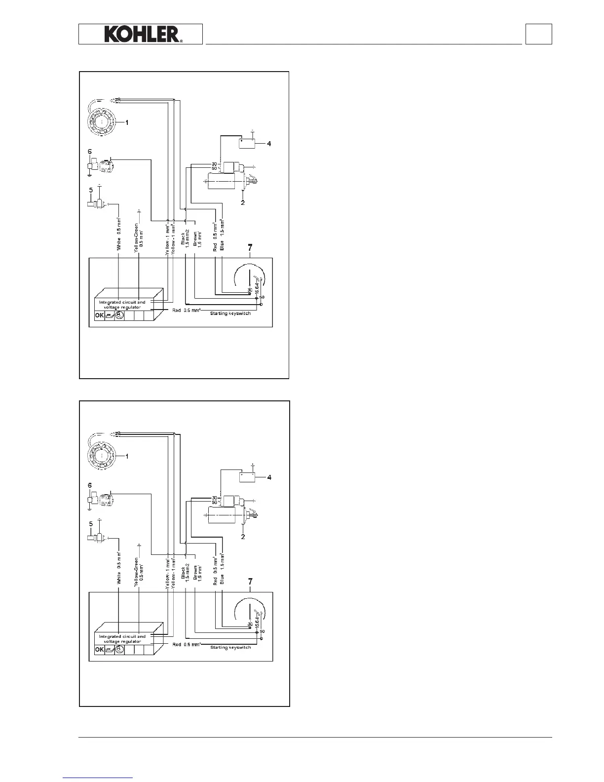
12V electric starter diagram with voltage regulator built into the
ignition panel
Components:
1 Alternator
2 Startermotor
4 Battery
5 Pressureswitch
6 Solenoidvalve
7 Ignitionswitch
12V electric ignition layout with motor protection (optional)
Components:
1 Alternator
2 Startermotor
4 Battery
5 Pressureswitch
6 Solenoidvalve
7 Ignitionswitch
8 Panel
KD 225_315_350_400_440 Workshop Manual_cod. ED0053029330_1° ed_ rev.00
Note: The battery, which is not supplied by KOHLER, should have
12Vnominalvoltageratingandacapacityofnotlessthan44
Ah/210Amp.offastdischargeintensity.
Note: The battery, which is not supplied by KOHLER, should have
12Vnominalvoltageratingandacapacityofnotlessthan44
Ah/210Amp.offastdischargeintensity.
 Loading...