53
Electrical System
22 690 01 Rev. -- KohlerEngines.com
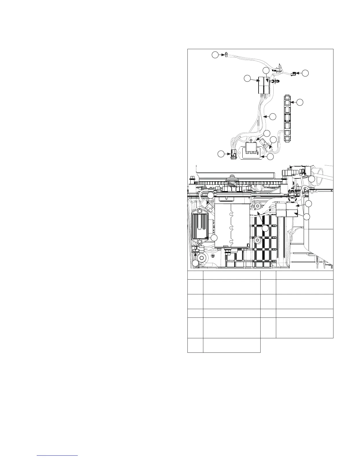
Stator Brake and Fuel Shut-off Relay Harness
Connections
A
B
E
C
H
I
F
D
K
J
D
J
F
G
H
G
E
A Stator Assembly B Wiring Harness
C
Stator Leads to
Rectifi er-Regulator
D Rectifi er-Regulator
E
2 Wire Stator
Connector
F Ignition Kill Wire
G Fuel Shut-Off Relay H Stator Brake Relay
I
Harness Routed
Between Starter and
Crankcase
J
Engine to Equipment
6 Pin Connector
K
Fuel Shut-off Solenoid
Connector
BLADE STOP STATOR BRAKE AND FUEL SHUT-OFF
CIRCUIT
Some engines are equipped with a fuel shut-off relay
and a stator brake relay. These relays are part of wiring
harness. Refer to FUEL SHUT-OFF RELAY CIRCUIT
(on previous pages) for troubleshooting fuel relay part of
circuit.
Blade stop stator brake circuit is provided as a safety
feature to ensure application can meet ANSI (American
National Standards Institute) application blade stop
requirements.
Circuit is activated if operator gets off of seat of
application while mower blade system is activated or in
certain reverse mow conditions.
Circuit is activated by taking ignition shutdown (kill) lead
to ground. This action turns on stator-brake relay which
shorts charging AC stator leads to produce a magnetic
fi eld that will counter or resist rotation of fl ywheel, along
with removing power from fuel solenoid. This added
resistance to rotation decreases amount of time it takes
for application deck blades to come to a full stop.
If relay needs replacement, wiring harness must be
replaced.
 Loading...