Vers. 111422 73
To connect, simply push the cable or the ferrule directly onto the corresponding hole.
To disconnect the cables, press lightly on the respective orange plate.
Solid cable section min (mm²) 0.2
Solid cable section max (mm²) 0.5
Section of braided cable min (mm²) 0.2
Section of braided cable max (mm²) 0.5
Flexible cable section with min ferrule without sheath (mm²) 0.25
Flexible cable section with max ferrule without sheath (mm²) 0.75
Flexible cable section with min ferrule with sheath (mm²) 0.25
Flexible cable section with max ferrule with sheath (mm²) 0.5
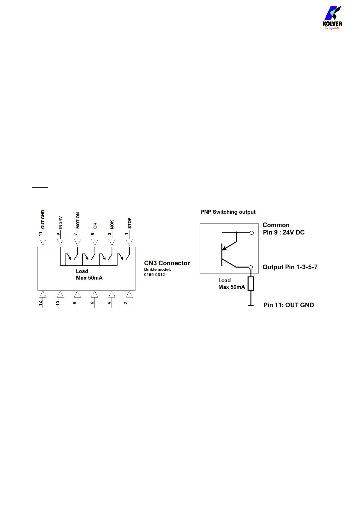
Note: you must supply a 24 VDC power source to Pin 9 to drive output signals 1-3-5-7, with
grounding reference to Pin 11:
The input signals 2-4-6-8 require PNP logic: supply 24 VDC with respect to the grounding
reference on Pin 10 to enable the corresponding function.
 Loading...