MAINTENANCE 4.16 WELD REPAIRS
441
Electrical Units in Cab Base, illustration Z23095B
1. Switch off all circuit breakers in the switch box (X2).
2. Remove the three green plugs from the sockets (X23 and
X24) on the master input signal module (E34). Remove the
two green plugs from the socket (X26) on the slave input sig-
nal module (E39).
3. Disconnect all plugs on the back of the multi monitor (E62)
4. Remove the wiring harness connector from electronic pump
controller CR700 (E61).
EMARK
Be sure to isolate Electronic Components of Special Equip-
ment.
Engine Electronics
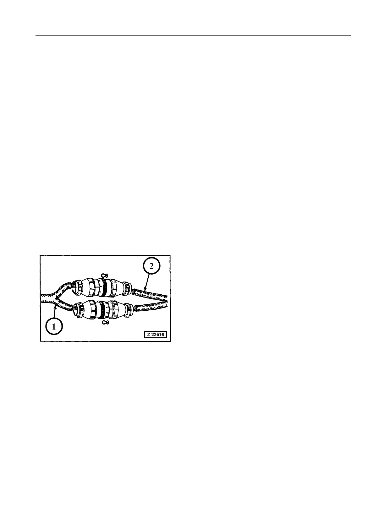
Disconnect the two Deutsch connectors (C5 and C6), illustration
Z 22516. The connectors are located on the LH engine side near
the flywheel housing.
For more information refer to the Operation and Maintenance
Manual CENTRY System, filed in Volume 2 Binder.
(1) - Engine harness
(2) - Shovel harness
4.16.4 AFTER FINISHING THE REPAIR WELDINGS ON THE
SUPERSTRUCTURE
After finishing the weld repairs connect all cable connectors which
have been disconnected. When connecting the two Deutsch con-
nectors (C5 and C6), make sure you hear a click.
When all electrical connections are established insert the battery
main switch keys.