OTHER ADJUSTMENTS CF5001 Field Service Ver.1.0 Sep 2003
2-140
II ADJUSTMENT
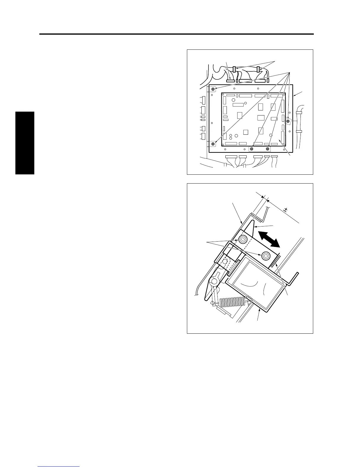
6. Remove the rear cover.
7. Unplug all connectors [2] from the FNS control
board (FNSCB) [1] and remove the wiring har-
ness from the clamp [3].
8. Remove 5 screws [4]. Then, remove the FNSCB
[1] with the bracket [5].
9. Loosen 2 screws [2] for the by-pass gate sole-
noid (SD705) [1] and adjust the position of SD
705 [1] based on the mark [5] to make the clear-
ance between the by-pass gate [3] and the by-
pass conveyance plate [4] to be within the stan-
dard value when SD705 [1] is off.
Standard value: A = 3.2 ± 0.5 mm
10. Reinstall the above parts following the removal
steps in reverse.
8050fs1079
[4]
[2]
[3]
[5]
[1]
8050fs1080
A=3.2 0.5mm
[5]
[2]
[1]
[4]
[3]