PARTS LAYOUT DRAWING CF5001 Field Service Ver.1.0 Sep 2003
6-24
VI DIAGRAMS
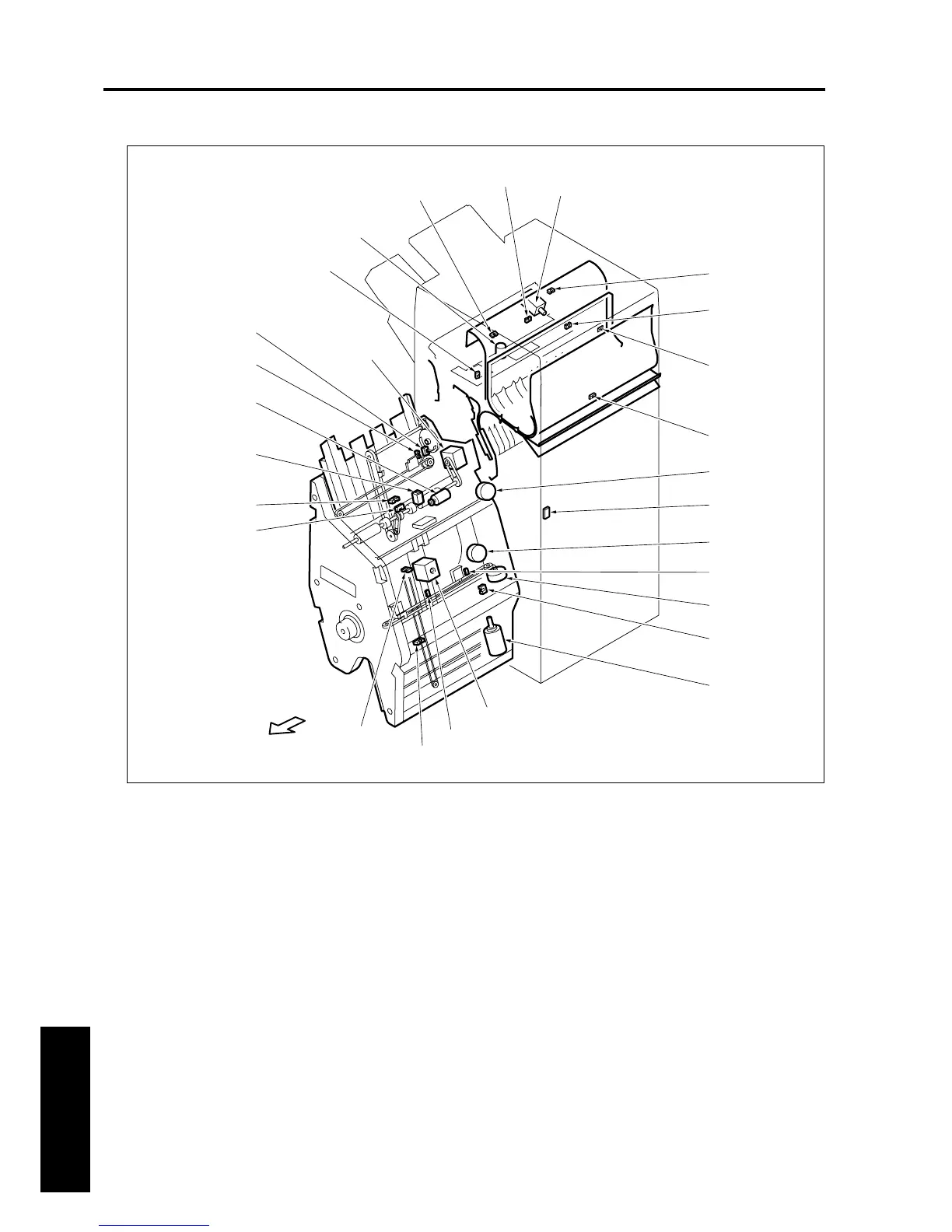
1.4 FN-120/FN-9 parts layout drawing
[1] Sub-tray paper exit sensor (PS701) [15] Stopper HP sensor (PS723) (FN-9 only)
[2] Paper exit opening HP sensor (PS712) [16] Stacker inlet sensor (PS705)
[3] Gate HP sensor (PS716) [17] Stacker no paper sensor (PS720)
[4] FNS inlet sensor (PS704) [18] Stacker auxiliary solenoid (SD702)
[5] Stapler movement motor (M711) [19] Stack auxiliary motor (M722)
[6] FNS interlock switch (MS701) [20] Alignment HP sensor/U (PS708)
[7] Clincher rotation motor (M704) [21] Paper exit belt HP sensor (PS709)
[8] Alignment HP sensor/L (PS724) (FN-9 only) [22] Stacker inlet motor (M713)
[9] Alignment motor/L (M716) (FN-9 only) [23] Shift HP sensor (PS718)
[10] Folding knife HP sensor (PS722) (FN-9 only) [24] Shift motor (M702)
[11] Folding knife motor (M719) (FN-9 only) [25] Main tray paper exit sensor (PS706)
[12] Stopper motor (M718) (FN-9 only) [26] Sub-tray full sensor (PS719)
[13] Clincher rotation HP sensor(PS714) [27] Paper exit opening solenoid (SD704)
[14] Folding passage sensor (PS726) (FN-9 only)
[3]
[2]
[1]
[4]
[5]
[6]
[7]
[9]
[10]
[11]
[14]
[15]
[16]
[17]
[18]
[19]
[20]
[21]
[22]
[23]
[24]
[25]
[26]
[27]
[13]
[12]
[8]
8050fs6701
FRONT