8 Connection
8.2 Connecting the processing unit
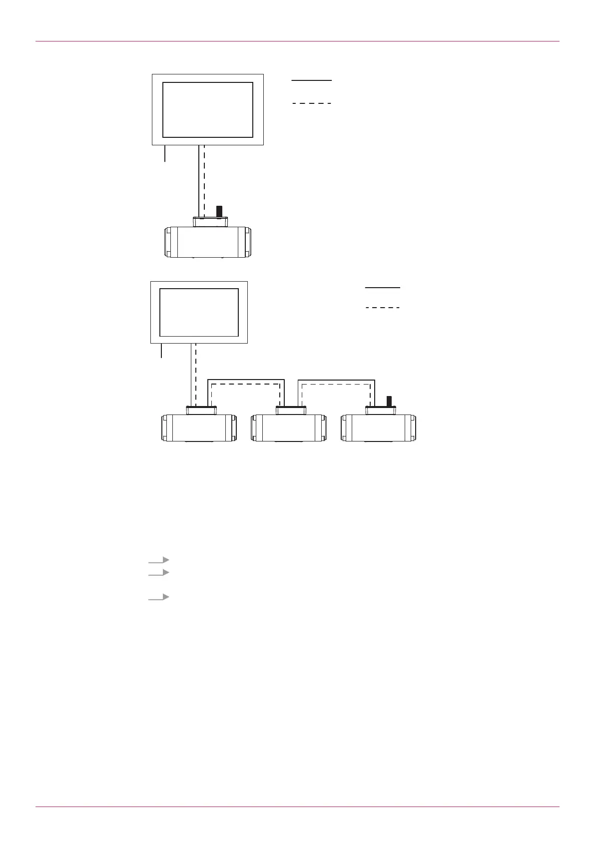
Fig.6: Connecting one processing unit
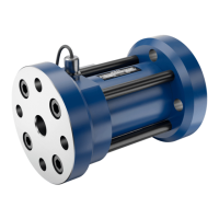
Fig.7: Connecting several processing units
1 Flowmeter with processing unit 5 Display device (HMI)
2 Flowmeter with processing unit 6 Power supply display device
3 Flowmeter with processing unit C1 Power supply processing unit
4 Terminating resistor C2 Connection Modbus RS-485
Requirement:
ü Modbus cable available for all the connections
1. Connect the Modbus output (MODBUS OUT) of the first processing unit with the display device.
2. Terminate the Modbus input (MODBUS IN) of the last processing unit with the terminating
resistor.
3. When connecting several processing units in series connect the output of a processing unit with
the input of the next processing unit.
Operating instructions
OIE 26en-GB Edition 2021-08
15