7 Installation, removal
7.1 Dangers during installation, removal
7 Installation, removal
7.1 Dangers during installation, removal
The following safety instructions must be strictly observed:
o Have all work only carried out by electricians.
o Do not take apart the electronic unit.
7.2 Installing the processing unit
One processing unit is assigned to exactly one flowmeter. The serial numbers of the processing unit
and of the assigned flowmeter are specified on the rating plate of the processing unit Ä Identifica-
tion,Page4.
The processing unit is mounted directly on the flowmeter.
For information on installing the processing unit please refer to the associated operating instructions of
the flowmeter.
7.3 Removing the processing unit
For information on removing the processing unit please refer to the associated operating instructions of
the flowmeter.
8 Connection
8.1 Dangers during connection work
The following safety instructions must be observed:
o Have all work only carried out by electricians.
8.2 Connecting the processing unit
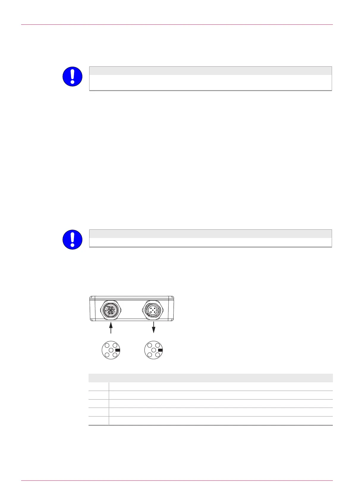
A maximum of 32 processing units can be connected in series. Modbus communication and power
supply are effected through a cable. The Modbus input of the last processing unit has to be terminated
with a terminating resistor.
4
3
2
1
5
4
3
2
1
5
MODBUS IN
MODBUS OUT
Fig.5: Pin assignment
Pin Description
1 Shield
2 DC power supply 10–30 V (+)
3 DC power supply 0 V (- or GND)
4 RS-485 A / + / RXTX-P (positive)
5 RS-485 B / – / RXTX-N (negative) / inverted
Tab.20: Pin assignment
14
OIE 26en-GB Edition 2021-08
Operating instructions