SID-X3N - Defining the SID-X3N Step-in Commander
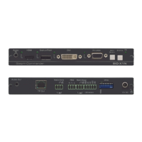
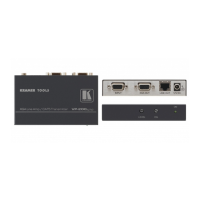
Figure 2 defines the rear panel of the SID-X3N.
Figure 2: SID-X3N Step-in Commander Rear Panel
AUDIO OUT 3.5mm Mini Jack
Connect to an unbalanced, stereo audio acceptor, (see
Section 4)
Connect to a compatible switcher, for example, VS-62H using an
HDMI cable
REMOTE STEP-IN
3-pin Terminal
Block
Connect to the anode of the remote Step-In LED indicator
Connect to the remote, Step-In switch, (see Section 5.1)
PROG RS-232 3-pin Terminal
Block
Connect to the PC via RS-232 to perform a firmware upgrade
REMOTE
SELECT 8-pin
Terminal Block
Connect to the anode of the remote Input Select LED indicator,
(see Section 4)
Connect to the remote, Input Select switch, (see Section 5.2)
LED HDMI,
DP, DVI and
UXGA
Connect to the anodes of the remote input indicators
(see Section 5.3)
Used to set the device behavior, (see Section 8)
Provides 5V DC power to a device, (max 1.5A)
Connect to supplied power adapter, center pin positive