SID-X3N - Connecting the SID-X3N
5.3 Connecting the Remote Input Selection LEDs
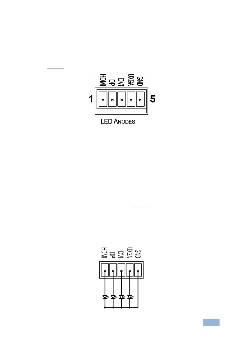
You can connect remote, input selection LEDS to the LED terminal block on the
rear panel of the SID-X3N to indicate which is the active input.
Figure 6 illustrates the connections from the terminal block to the LEDs.
Figure 6: Remote Input Indicator LED Connections
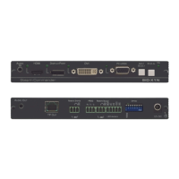
To connect remote input indicator LEDs:
1. Connect pin 1 from the terminal block to the anode of the remote HDMI
indicator LED.
2. Connect pin 2 from the terminal block to the anode of the remote DP
indicator LED.
3. Connect pin 3 from the terminal block to the anode of the remote DVI
indicator LED, (see the example in Figure 7).
4. Connect pin 4 from the terminal block to the anode of the remote UXGA
indicator LED.
5. Connect pin 5 from the terminal block to the cathode of each LED.
Figure 7: Remote Input Indicator LED Wiring