KRAMER: SIMPLE CREATIVE TECHNOLOGY
Your VS-88HDxl 8x8 3G SD/HD-SDI Matrix Switcher
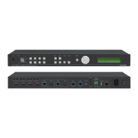
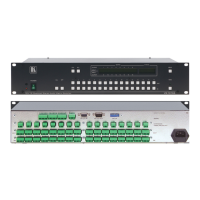
Table 1: Front Panel VS-88HDxl 8x8 3G SD/HD-SDI Matrix Switcher
1 IR Receiver The yellow LED illuminates when receiving signals from the infrared remote
control transmitter
2 POWER LED Illuminates when the unit is ON
3 ALL Button Pressing ALL followed by an INPUT button, connects that input to all outputs
4 OFF Button Pressing OFF+OUT disconnects that output from the inputs;
pressing OFF+ALL disconnects all the outputs;
a long press toggles between dual link and normal mode
5 IN SELECT Buttons Select the input to switch to the output;
long presses on buttons IN1 to IN5 change the genlock timing (see
Table 5)
6 OUT SELECT Buttons Select the output to which the input is switched
7 STO (STORE) Button Pressing STO followed by an IN / OUT button stores the current setting
8 RCL (RECALL) Button Pressing the RCL button and the corresponding INPUT / OUTPUT key recalls a
setup from the non-volatile memory
9 LOCK Button A long press toggles activation/inactivation of the front panel buttons;
pressing LOCK+OUT2 selects Protocol 2000; pressing LOCK+OUT3 selects
Protocol 3000
10 TAKE Button Pressing TAKE toggles the mode between the CONFIRM mode and the AT
ONCE mode (user confirmation per action is unnecessary)
11 7-segment Display Displays the selected input switched to the output (marked above each input)
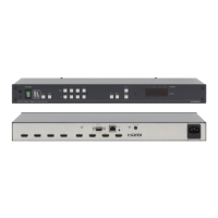
Table 2: Rear Panel VS-88HDxl 8x8 3G SD/HD-SDI Matrix Switcher
12 GENLOCK BNC Connector Connects to the genlock source
13 TERM HI-Z/75Ω Pushbutton Press to terminate the genlock source (75Ω) or release for looping
14 LOOP BNC Connector Connects to the genlock connector of the next unit in the line
15 INPUT BNC Connectors Connects to the serial digital video sources
16 RS-232 9-pin D-sub (F) Port Connects to the PC or the remote controller
17 PROG/RS-485 TERM
DIP-switches
PROG DIP-switch enables microcontroller firmware upgrade
RS-485 TERM DIP-switch terminates the RS-485 line with a 120Ω load
18 RS-485 Terminal Block Port Pins B (-) and A (+) are for RS-485;
Pin G may be connected to the shield (if required)
19 ETHERNET RJ-45 Connector Connects to the PC or other Serial Controller through computer networking
LAN
20 MACH # DIP-switches DIP-switches 1-4 for setting the Machine Address of the unit
21 ETH RESET Button Press to reset to factory default definitions
22
:
IP number − 192.168.1.39, Mask – 255.255.0.0, Gateway – 0.0.0.0
OUTPUT BNC Connectors Connect to the serial digital video acceptors
23 REMOTE IR 3.5mm Mini Jack Connect to an external IR receiver unit for controlling the machine via an IR
remote controller (instead of using the front panel IR receiver)
2
24
Power Connector with Fuse AC connector enabling power supply to the unit
25 Power Switch Turns the power to the unit ON and OFF
1 First disconnect the power cord and then connect it again while pressing the ETH Factory Reset button. The unit powers up
and loads its memory with the factory default definitions and erases all stored presets
2 Optional. Can be used instead of the front panel (built-in) IR receiver to remotely control the VS-88HDxl (only if the
internal IR connection cable has been installed) (See section
4.1)
 Loading...